Download
1 / 14
140 likes | 278 Vues
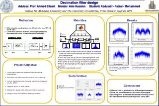
This paper explores the innovative design of analogue filter IP cores aimed at enhancing design reuse in System on Chips (SoCs). It addresses the challenges of high-level description trade-offs and emphasizes the significance of redesigning for specific specifications and manufacturing processes. Key design considerations include switched current methodologies, circuit design techniques, and automation tools that facilitate rapid and efficient filter design. The results presented showcase the benefits of wave filter methodologies and integrated CAD tools, offering insights into future work for extending the filter library.

E N D
Bashir Al-Hashimi Reuben Wilcock bmah@ecs.soton.ac.uk rw01r@ecs.soton.ac.uk Analogue Filter IP Cores for Design Reuse
Outline • Introduction and Motivations • Analogue Filter IP Core Design • Example Results • Concluding remarks
Introduction • System on Chips (SoC) employ IP cores • Analogue IP core design is demanding • Difficult to trade as high level description • Correct operation depends on many factors Important to redesign for particular specifications and process to ensure functionality
Analogue Filter IP Core Design • What are the considerations? • Circuit design technique • Filter Methodology • Automation
Solution: Switched Current • Designs based on current mirrors • No linear passive components • Current mode allows low Vdd • High performance cells available Circuit Design Technique • Requirements • Simple, easily designed blocks • No high quality passive components • Compatible with present and future processes • High performance Solution ?
Solution: Wave Filters • Ideal for Switched Current • Easily designed blocks • Based on LC ladders • Bilinear transform Filter Methodology • Requirements • Suitable for Switched Current • Regular structures and simple design procedure • Based on LC ladder to inherit low sensitivity • Bilinear transform so Nyquist limit can be approached Solution ?
Solution: SKILL tool • Automate hand-calculations • Integrated in Cadence • Manual/Automatic optimisation loops Automation • Requirements: • Increase productivity • Transistor level simulations • Optimisation Solution ?
Step 1: Passive Filter Design • De-normalise values • Frequency response • Choose filter type/function/order • Normalised component values
Step 2: Wave Filter Design • Decide cutoff/sample ratio • Coefficients are calculated • Optimise [Yufera ’94] • Frequency response from behavioural models
Step 3: Memory Cell Design • S2I memory cell [Hughes ’00] • Trade off design parameters • First cut design calculated • DC, transient simulations • Optimise for gm, Cgs, Ctot, Switch Ron and settling
Step 4: Complete Filter Design • Save all design variables, dimensions and coefficients to a single file • Schematic representing entire transistor level design is opened • Spectre RF used to give an AC response in minutes • Revisit steps 1 – 3 as necessary
Schematic Hierarchy • Parameter passing with pPar(“”) • Hierarchy from top to transistor level
Conclusions • Switched Current has good potential for IP cores • Wave is suitable as a filter methodology • Automation tools should be integrated into powerful CAD packages • Our tool allows a designer to rapidly develop Switched Current analogue filter cores. • Future work will involve • Extending the filter library • Including Class AB cell as alternative to S2I • May include layout (step 5)
Contact Reuben Wilcock Electronic Systems Design Department of Electronics and Computer Science University of Southampton United Kingdom rw01r@ecs.soton.ac.uk