Decimation filter design
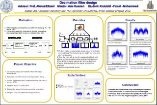
Decimation filter design Advisor: Prof. Ahmed Eltawil Mentor: Amr Hussien Student : Abdulatif - Faisal - Mohammed. This is the inserted signal . This is the signal after upsampling and we

Decimation filter design
E N D
Presentation Transcript
Decimation filter design Advisor: Prof. Ahmed Eltawil Mentor: AmrHussien Student: Abdulatif - Faisal - Mohammed • This is the inserted signal .This is the signal after upsampling and we • observe the increasing of sample rate. • This is the signal after downsampling This is the output signal and we observe • and we observe the decreasing that we can recover the original signal. • of sample rate. • R • J • First we insert an input audio sound saved in computer or we can use the microphone and insert our voice and plot the spectrum. • Then the input will go into the upsampling block and add zeros for the original signal and plot the spectrum. • Use a filter to avoid aliasing and plot the spectrum • We do downsampling to the signal and plot the spectrum. • Test the output audio sound. Different audio sound systems use different rates (e.g. 44.1 , 48 and 96 KHz) . Conversion operation is carried out through upsampling , downsampling or both in case of a rational value SRC. X[n] Xe[n] Xi[n] Xr[n] Xd[n] Motivation Main Idea Results decimator interpolator Lowpass filter Gain = 1 Cutoff = ᴨ /M Lowpass filter Gain = L Cutoff = ᴨ /L M Hv M L F Learn how to design and implement filters with design specifications . Be familiar with different kinds of windows used in filtering . Convert the sampling rate of a digital signal from one value to another (SRC). Apply the idea to an audio system. Maintain the quality of the audio sound after re-sampling . Study the trade-offs of different filtering techniques. Project Objective MATLAB Graphical user interface. Tools/Testbed • Different kind of window have different performance. • Filters are useful to remove the noise from signal. • Choosing filter is maintain the quality of audio sound. • We can recover the original signal by using SRC Conclusions