Download

1 / 8
80 likes | 302 Vues
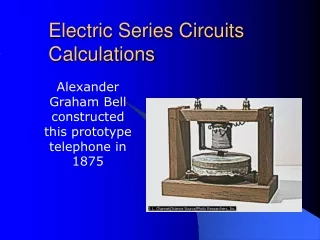
Electric Series Circuits Calculations. Alexander Graham Bell constructed this prototype telephone in 1875. Resistors. Lamps or bulbs (light energy) Electric Motors ( mechanical energy) Heaters Speakers Carbon Paper. Ohms law . R= Resistance (control of the flow of electrons)

E N D
Electric Series Circuits Calculations • Alexander Graham Bell constructed this prototype telephone in 1875
Resistors • Lamps or bulbs (light energy) • Electric Motors ( mechanical energy) • Heaters • Speakers • Carbon Paper
Ohms law • R= Resistance (control of the flow of electrons) • I = Current ( the amount of electron “flow” ) • V= Volts (the “pressure" or potential of the charges V = I R
Ohm Law’s Calculation • The diagram shows two resistors connected in series to a 20.-volt battery. If the current through the 5.0-ohm resistor is 1.0 ampere, the current through the 15.0-ohm resistor is
Ohm Law Solution • Rt = R1 + R2 • Rt =15 W + 5 W • V=I R • 20 v = I (20 W) • 1A = I
Voltage in a Series Circuit • The net change in voltage “around” the circuit is equal to zero • Vt = V1 + V2 + V3 + ……… • The Voltage “divider” is the resistor • V1 = I R1 , V2 = I R2, V3 = I R3 • Note: The current ( I ) is constant throughout the Series circuit
Resistance in a Series Circuit • Each resistor adds to the Total resistance of the circuit (equivalent resistance) • Rt = R1 + R2 + R3 + ……… • The Voltage “divider” is the resistor • V1 = I R1 , V2 = I R2, V3 = I R3 • Note: The current ( I ) is constant throughout the Series circuit • The Amperes are constant • I = I1 = I2 = I3
Summary • In a Series Circuits the amperes remain constant throughout the circuit • Resistors control the voltage and current of power sources • The Total voltage is equal to the sum of the individual voltages • The Total resistance is equal to the sum of individual resistance