Download
1 / 17
170 likes | 302 Vues
The initial findings of the Delay Chip Test Board with LVDS clocks, SPI control, and test procedures for optimal performance evaluation. Discover the implications of adjusting the coarse voltage, measuring operating frequencies, clock jitter, delay line linearity, and more.

E N D
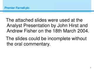
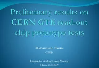
Preliminary results of the delay chip Joan Mauricio Ferré Xavier Ondoño (2013/09/20)
Reminder • Features: • 1 LVDS clock input. • 12 independent LVDS clock outputs. • 25 configurable clock phases. • 1-ns granularity. • Radiation-hard design. • ~250 mW of power consumption. • Slow control: • SPI interface. • SEU tolerance. Control Voltages Power / Ground LVDS Clocks Slow Control (SPI)
Reminder (externallyshorted) powRstOut coarse Reset Block Mux clkINT<3:0> nRst powRstIn vRef rst ··· VCDL+Mux clkT&H<3:0> clkRef PhaseComp + ChargePump nRst Config Status SPI Slave !en, clkdin, dout vControl<3:0> nRstPump AnalogConfig. coarse vControl Digital Config. VCDL+Mux clkADC<3:0> Diff. LVDS Clock Config nRst Diff.CMOSClock Slow Control
Delay Chip Test Board • Features: • QFN-48 socket. • QFN-48 footprint. • Selectable clock input: • LVDS (via RJ-45). • Single Ended (via Lemo). • Single Ended LVDS driver. • Reset button to preset Config. Regs. • Coarse is adjusted via potentiometer. • Mezzanine mode: • Powered via LAL’s FEB (3.3 VDC). • SPI master is the FPGA of the FEB. • Standalone mode: • Externally powered (3.3 VDC). • 3rd party SPI master is plugged into the board.
Delay Chip Test Board Single Ended to LVDS(DS92LV010A). LVDS input (RJ-45). Single Ended input (Lemo). 12 x LVDS clock output. Power reset jumper. LVDS reference clock. Configuration registers reset. Coarse potenciometer. External power supply (standalone mode). 3rd party SPI master (standalone mode). FEB SPI master (mezzanine mode). VControl monitoring (DLL pumps). FEB power supply (mezzanine mode). SPI debugging ports.
Performed tests • Optimal Coarse voltage adjust. • Minimum – maximum operating frequencies. • VControl noise. • Output clock jitter. • Delay line linearity. • Slow control Frame Error Rate (FER).
Optimal Coarse voltage adjust • The VCDL is controlled by: • Internal phase detector (fast variations). • External coarse adjust (process variations). • Why coarse must be adjusted? • To balance the current contribution of P and N transistors in the Starved Inverter. • Otherwise rise and fall time will be unequal. • Phase Detectors will lock the DLL when delay ≠ 25 ns.
Optimal Coarse voltage adjust • How test is performed? • One of the Delay lines is set to phase #0. • Phase #0 (respect to the clock generator) is measured. • Delay line is now set to phase #24. • Phase #24 is measured. • If Phase #24 – Phase #0 is close to 24 ns, ok. Otherwise, change coarse voltage (with the potentiometer) and try again.
Minimum – maximum operating frequency measurement • How the test is performed? • We repeat the previous test for different input frequencies. • For low frequencies, vControl↑ and coarse↓. • Coarse is manually decreased until the delay line is balanced. • For low frequencies, vControl↓ and coarse↑. • Coarse is set to 3.3V and we wait for vControl = 0V.
VControl noise • VControl waveform is catched.
Output clock jitter • How test is performed? • Clock σjitter is measured after the LVDS driver. • Clock σjitter is measured in the LVDS clock outputs. • The jitter added by the delay line is the difference between the input and the output σjitter.
Delay line linearity • How test is performed? • Clockphase # issweptfrom 0 to 24 and delta time isannotated. • Then:
Slow Control Frame Error Rate • SPI frames look like this: • Random data is written into the 8 config. Registers. • Data is read back and compared. • FER < 1e-5@ 10 Mbps. • Writes OK @ 30 Mbps but reads NOT OK. Additional clk pulse
Possible improvements (1) • Slewratecorrection: • Pros: phase detector willnotdepend on coarseandvControl. • Cons: mismatchmaycauseIntegrated Non-Linearity.
Possible improvements (2) • Slow Control: • Standard SPI. • The SPI Slave FSM has to be changedto makethelastclockpulseUnnecessary. Additional clk pulse