Download
1 / 17
170 likes | 186 Vues
This update discusses the progress and milestones achieved in the development of a lock acquisition procedure for a detuned Resonant Sideband Extraction (RSE) interferometer, aiming to closely match the optical design of Advanced LIGO.

E N D
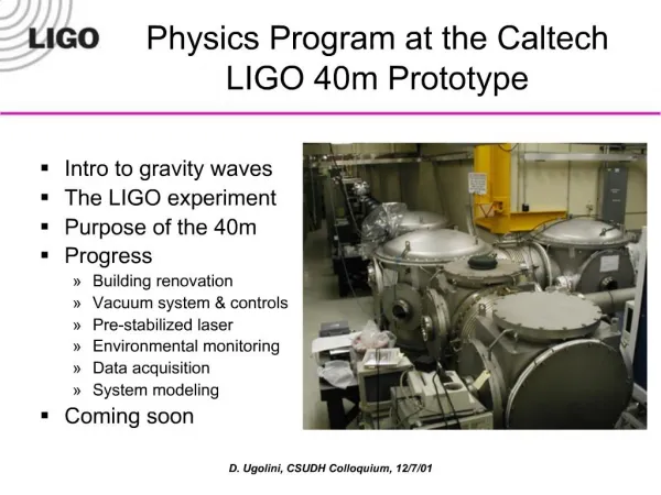
Experimental update from the 40m team 40m TAC meeting May 13, 2005 O. Miyakawa, Caltech and the 40m collaboration 40m meeting, May 2005
Caltech 40 meter prototype interferometer Objectives • Develop lock acquisition procedure of detuned Resonant Sideband Extraction (RSE) interferometer, as close as possible to Advanced LIGO optical design BS • Characterize noise mechanisms • Verify optical spring and optical resonance effects • Develop DC readout scheme • Extrapolate to AdLIGO via simulation • etc. SRM PRM Bright port Dark port X arm Y arm 40m meeting, May 2005
Important Milestones 2003 Sept. Installation of Four TMs and BS:done Oct. Lock of FP Michelson :done 2004 Feb. Installation of Power Recycling Mirror (PRM) ,Signal Recycling Mirror (SRM) :done June.Installation Mach-Zehnder to eliminate sideband of sideband :done Oct. DRMI locked using Double Demodulation(DDM) :done Nov. Both arms locked with off-resonance :done 2005 RSE :in progress Full lock is soon! 40m meeting, May 2005
Carrier (Resonant on arms) -f2 -f1 f1 f2 AdLIGO signal extraction scheme ETMy • Two modulations are used to separate high finesse, 4km long arm cavity signals fromCentral part (Michelson, PR, SR) signals. • Only + f2is resonant on SRC • Unbalanced sidebands of +/-f2 make error signal of Central part • Arm cavity signals are extracted from beat between carrier and f1 or f2. • Central part (Michelson, PR, SR) signals are extracted from beat between f1 and f2, not including arm cavity information. 4km ITMy f2 f1 ETMx PRM ITMx BS 4km SRM • Single demodulation • Arm information • Double demodulation • Central part information 40m meeting, May 2005
ETMy Ly ITMy lsy ETMx PRM Laser ly ITMx BS lx Lx lsx SRM PO SP AP 5 DOF for length control Signal Extraction Matrix (in-lock) Common of arms Differential of arms Power recycling cavity Michelson Signal recycling cavity : L=(Lx Ly) / 2 : L=Lx Ly : l=(lx ly) / 2 : l=lx ly : ls=( lsx lsy) / 2 40m meeting, May 2005
Lock Acquisition of Detuned RSE 1. lock central part 2. lock arm cavities ETMy ITMy PRM ITMx BS ITMy ETMx PRM ITMx BS Step 2 Step 1 Step 3 SRM SRM • Central part: not disturbed by carrier resonance on arm cavity (but disturbed by sidebands resonance) • Lock acquisitionAfter lock: l- : dither @ 1200 Hz DDM@AP l+ : 33MHz@SP DDM@SP ls : DDM@PO DDM@PO • Arm cavities: not disturbed by locked central part 40m meeting, May 2005
1 ~ LPF LPF LPF LPF Looking for good signal for lock acquisition • Dither locking for l- signal • Divide signal by inside power • Good cancellation of power recycling ITMy PO ITMx BS Laser PRM SRM SP AP a few kHz VPO (VPO)’ VAP (VAP)’ Digital calculation DVl 40m meeting, May 2005
Carrier 33MHz 166MHz ITMy Carrier ITMx BS Unbalanced 166MHz PRM DDM PD 33MHz SRM DDM PD OSA DDM PD Belongs to next carrier Belongs to next carrier DRMI lock using double demodulation with Unbalanced sideband by detuned cavity August 2004 • DRMI locked with carrier resonance (like GEO configuration) November 2004 • DRMI locked with sideband resonance (Carrier is anti resonant preparing for RSE.) Typical lock acquisition time : ~10sec Longest lock : 2.5hour 40m meeting, May 2005
Struggling lock acquisition for Arms Problems • Too fast mirror motion on Xarm due to poor ITMX damping(?) • High recycling gain of ~15 produces large coupling between two arms • Very High combined finesse of ~18000 • Slow sampling rate of 16kHz for direct lock acquisition 40m meeting, May 2005
For Arm lock We have two steps. • Middle resonance of carrier using “Off-resonant DC lock” scheme …done • Remove offset to have full resonance of carrier …in progress 40m meeting, May 2005
Off-resonant DC lock scheme for arm cavity Error signal is produced by transmitted light as Resonant Lock Off-resonant Lock point 40m meeting, May 2005
Arm power Xarm lock Yarm lock Error signal Offset lock Offset lock Ideal lock point Off resonant DC transmissionArm lock with DRMI DRMI with single arm lock • Lock acquisition time ~1 min • Can be switched to RF signal • Full carrier was stored in each arm cavity separately Both arms lock with DRMI • Lock acquisition time ~10 min • Lasts ~ 10 min • Can be switched to RF signal • ~200 times dynamic range of carrier resonance >>Needs second transmitted PD (low noise/high dynamic range) 40m meeting, May 2005
(POX/TrX), (POY/TrY) (POX/TrX) + (POY/TrY), (POX/TrX) – (POY/TrY) Carrier 33MHz 166MHz SP166/PRC, AP166/PRC (TrX + TrY), (TrX – TrY) / (TrX + TrY) The way to full RSE Ideas for arm control signal Off-resonant arms using DC lock DRMI using DDM RSE ETMy Shutter ITMy PRM ETMx ITMx BS Shutter SRM Done Done In progress 40m meeting, May 2005
ETMY ITMY ITMX ETMX PRM BS SRM e2e SIMULATION:4Om/AdvLIGO package optical configuration IFO with Arms IFO Central part 40m meeting, May 2005
e2e SIMULATION:4Om/AdvLIGO package • E2E validation of DC fields comparing with TWIDDLE results: good agreement ! • E2Etransfer functions simulations (and comparison with TWIDDLE ones) of DOF at SP, AP and PO shaking the end mirrors with white noise • at different demodulation frequencies : • (33,133,166,199) MHz I signal E2E TWIDDLE E2E Q signal TWIDDLE Example: DARM @ AP166 MHz TWIDDLE and E2E comparison
DC Readout at the 40m • Homodyne detection (via a DC readout scheme) has been chosen as the readout scheme for AdLIGO. • DC Readout eliminates several sources of technical noise (mainly due to the RF sidebands): • Oscillator phase noise • Effects of unstable recycling cavity. • The arm-filtered carrier light will serve as a heavily stabilized local oscillator. • Perfect spatial overlap of LO and GW signal at PD. • DC Readout has the potential for QND measurements, without major modifications to the IFO. • We can use a 3 or 4-mirror OMC to reject RF sidebands. • Finesse ~ 500 • In-vacuum, on a seismic stack. • The DC Detection diode • an aluminum stand to hold a bare photodiode, and verified that the block can radiate 100 mW safely. 40m meeting, May 2005
The Diode from SRM From SRM OMC Beam Steering :A preliminary layout is ready to go Existing in-vac seismically isolated optical table Mike Smith has designed a compact, monolithic MMT, similar to our input MMT. We’ll be using spherical mirrors. This will actually be the second PZT steering mirror. The first mirror after the SRM will also be a PZT steering mirror. • Ready for a review in late this month 40m meeting, May 2005