Download
1 / 68
680 likes | 699 Vues
Learn about the Caltech 40m Prototype Detuned RSE Interferometer and its potential for gravitational wave detection. Discover the advanced optical configurations and noise reduction techniques used in the system.

E N D
The Caltech 40m Prototype Detuned RSE Interferometer Robert Ward NAOJ seminar March 1, 2006 Osamu Miyakawa, Rana Adhikari, Matthew Evans, Benjamin Abbott, Rolf Bork, Daniel Busby, Hartmut Grote, Jay Heefner, Alexander Ivanov, Seiji Kawamura, Michael Smith, Robert Taylor, Monica Varvella, Stephen Vass, and Alan Weinstein NAOJ seminar, March 1, 2006
Michelson interferometer as a gravitational wave detector • Gravitational wave detection using Michelson interferometer • Signal and power enhancement using Fabry-Perot cavity in each arm • Power enhancement using Power Recycling FP cavity FP cavity Laser BS FP cavity FP cavity PRM Laser BS NAOJ seminar, March 1, 2006
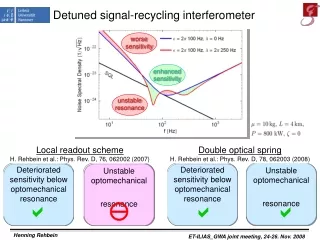
Advanced LIGO optical configuration • LIGO:Power recycled FPMI • Optical noise is limited by Standard Quantum Limit (SQL) • AdvLIGO:GW signal enhancement using Detuned RSE • Two dips in the quantum noise due optical spring, optical resonance • Has the potential to beat the SQL QND detector • Or allows quantum noise curve to be optimized in the presence of thermal noise FP cavity Power PRM FP cavity Laser BS GW signal Detuning NAOJ seminar, March 1, 2006
AdLIGO noise curve Fight the Fundamental Noise Sources: • Seismic • Thermal • Quantum Bench Active Seismic Isolation External Seismic Pre-Isolation Quadruple pendulum suspensions 40 kg, fused silica Test Masses 125W Laser NAOJ seminar, March 1, 2006
Resonant Sideband Extraction andSignal Recycling • Resonant Sideband Extraction(RSE) • Decrease storage time of GW signal in IFO • Allows high finesse arm cavities • Low power recycling, or power recycling not required • Less thermal effects • Signal Recycling(SR) • Increase storage time of GW signal in IFO • Low finesse arm cavities, or arm cavities not required • High power recycling required, so-called dual recycling(DR) • Higher thermal effects AdLIGO LCGT LIGO VIRGO TAMA300 GEO600 NAOJ seminar, March 1, 2006
Caltech 40 meter prototype interferometer Objectives • Develop a lock acquisition procedure for suspended-mass detuned RSE interferometer with power recycling, preferably one that will be applicable to Advanced LIGO BS SRM PRM • Characterize and optimize optical configuration (for robust control and sensitivity) • Characterize noise mechanisms • Develop DC readout scheme • Test QND techniques • Extrapolate to AdLIGO via simulation • Prototyping will yield crucial information about how to build and run AdLIGO Bright port Dark port X arm Y arm NAOJ seminar, March 1, 2006
FSS MOPA126 PMC VCO AOM Pre-Stabilized Laser(PSL)and 13m Mode Cleaner(MC) BS East Arm • 10W MOPA126 • Frequency Stabilization Servo (FSS) • Intensity Stabilization Servo • Pre-Mode Cleaner (PMC) • 13m Mode Cleaner ITMx ETMx ITMy PSL 40m arm cavity South Arm Mode Cleaner 13m MC Detection bench ETMy NAOJ seminar, March 1, 2006
Each optic has five OSEMs (magnet and coil assemblies), four on the back, one on the side The magnet occludes light from the LED, giving position Current through the coil creates a magnetic field, allowing mirror control LIGO-I type single suspension NAOJ seminar, March 1, 2006
40m Sensitivity Not very likely that we’ll actually detect any gravitational waves here, but hopefully we’ll learn some things about operating interferometers, especially about the quantum noise. Bench NAOJ seminar, March 1, 2006
40m DARM Optical Plant UGF The 40m operates in a detunedRSEconfiguration, which gives rise to two peaks in the DARM transfer function: • Optical Resonance • Optical Spring NAOJ seminar, March 1, 2006
IFO DARM/CARM FWHM Carrier frequency Sideband amplitude [a.u.] slope related to spring constant fsig LSB USB frequency offset from carrier [Hz] Detune Cartoon IFO Differential Arm mode is detuned from resonance at operating point SRC DARM IFO Common Arm mode is detuned from resonance at intial locking point • Responses of GW USB and GW LSB are different due to the detuning of the signal recycling cavity. PRC CARM NAOJ seminar, March 1, 2006
PRM Signal Extraction Scheme • Arm cavity signals are extracted from beat between carrier and f1 or f2. • Central part (Michelson, PRC, SRC) signals are extracted from beat between f1 and f2, not including arm cavity information. • Only +f2 sideband resonates in combined PRC+SRC Carrier Single demodulation Arm information -f2 -f1 f1 f2 Double demodulation Central part information NAOJ seminar, March 1, 2006
ETMy Phase Modulation f1=33MHz f2=166MHz Ly=38.55m Finesse=1235 ITMy lsy PRM ly ITMx BS lx Lx =38.55m Finesse=1235 lsx SRM PO SP AP 5 DOF for length control Signal Extraction Matrix (in-lock, DC) 40m Common of arms Differential of arms Power recycling cavity Michelson Signal recycling cavity : L=(Lx Ly) / 2 : L=Lx Ly : l=(lx ly) / 2 =2.257m : l=lx ly = 0.451m : ls=( lsx lsy) / 2 =2.15m ETMx Laser NAOJ seminar, March 1, 2006
Carrier -f2 -f1 f1 f2 Disturbance by sidebands of sidebands Original concept Real world • Sidebands of sidebands are produced by two series EOMs. • Beats between carrier and f2 +/-f1 disturb central part. Carrier -f2 -f1 f1=33MHz f2=166MHz 199MHz 133MHz NAOJ seminar, March 1, 2006
EOM1 EOM2 Mach-Zehnder interferometer on 40m PSLto eliminate sidebands of sidebands Mach-Zehnder interferometer with no sidebands of sidebands Series EOMs with sidebands of sidebands PMC trans f2 PZT f1 f2 Locked by internal modulation EOM2 f1 To MC EOM1 PD PMC transmitted to MC NAOJ seminar, March 1, 2006
Real Time Digital Control System 16kHz Sampling Rate Suspension controllers Fiber communication network Length Sensing and Control Interface to Operators Data Acquisition Also have an extensive slow controls network (EPICS) NAOJ seminar, March 1, 2006
Digital length sensing andcontrol system D/A D/A AP166 A/D mixer Output to suspensions Feedback filters Demodulated signal from PD Provides great flexibility to try out new control/locking schemes Easy to optimize control matrix NAOJ seminar, March 1, 2006
Digital Controller • Flexibility • digital filtering • smooth signal handoff • Diagnostics • arbitrary transfer functions • Reconfigurability • construct new control links, servos rapidly • quickly change MIMO servo filter • Optimization • can do automatic matrix diagonalization • Automation NAOJ seminar, March 1, 2006
Automation of Routine Tasks • Using the digital control system, we use shell scripts to automate routine tasks. Restores alignment of ETM, ITM, mis-aligns other optics, sets up loop gains and control flow, and engages lock acquisition routine. Steers ITM to center transmitted beam on QPD, dithers input beam and ETM alignment, servos to minimize dither signal in power level. NAOJ seminar, March 1, 2006
Control Setting Log (conlog) Constantly records all digital control settings (thousands of channels). Log files accessible through a simple web interface Useful for operators, commissioners, and data analysts. NAOJ seminar, March 1, 2006
40m Goal #1: Develop a Lock Acquisition procedure for AdLIGO • Version 1.0: • Basically a “Brute Force” technique • All optics are aligned, all DOFs are swinging. • Do some fast normalization, switching on/off of feedback: try to grab control without pumping too much energy into the system • Works much better with large available signals, strong actuators. • Suitability of procedure for AdLIGO to be extrapolated via simulation. NAOJ seminar, March 1, 2006
40m Lock Acquisition part I: Off-resonant lock scheme for a single cavity Transmitted light is used as Resonant Lock Off-resonant Lock point 10x higher finesse than LIGO NAOJ seminar, March 1, 2006
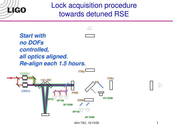
40m Lock acquisition procedure (v 1.0) Start with no DOFs controlled, all optics aligned. ITMy 166MHz ITMx 13m MC BS 33MHz PRM PO DDM SP33 SRM SP166 SP DDM AP166 AP DDM NAOJ seminar, March 1, 2006
1/sqrt(TrY) 40m Lock acquisition procedure (v 1.0) DRMI + 2arms with CARM offset MICH: SP33Q PRC: SP33I SRC PO133I XARM: DC lock YARM DC lock Average wait : 3 minute (at night, with tickler) Less than 1% of maximum circulating power ITMy 166MHz ITMx 13m MC 1/sqrt(TrX) BS 33MHz PRM T=7% PO DDM SRM SP166 SP33 T=7% I SP DDM Q AP166 AP DDM NAOJ seminar, March 1, 2006
-1 40m Lock acquisition procedure (v 1.0) All done by script, automatically Short DOFs -> DDM DARM -> RF signal CARM -> DC signal 1/sqrt(TrX)+ 1/sqrt( TrY) CARM -> Digital CM_MCL servo CARM + + DARM ITMy 166MHz ITMx 13m MC BS 33MHz PRM PO DDM SRM SP33 SP166 SP DDM To DARM AP166 AP DDM AP166 / sqrt(TrX+TrY) NAOJ seminar, March 1, 2006
-1 40m Lock acquisition procedure (v 1.0) script Reduce CARM offset: 1. Go to higher ARM power (10%) 2. Switch on AC-coupled analog CM servo, using REFL DC as error signal. 3. Switch to RF error signal (POX) at half-max power. 4. Reduce offset/increase gain of CM. DARM ITMy 166MHz 1900W ITMx 13m MC BS SP166 33MHz PRM PO DDM SRM SP33 SP DDM To DARM REFL AP166 AP DDM AP166 / (TrX+TrY) NAOJ seminar, March 1, 2006
DARM Optical response with fit to Buonanno & Chen formula DARMin1 / DARMout ---------------------------- XARMin1 / XARMout times arm cavity pole. Yields optical response, taking out pendulum, analog & digital filtering, etc. XARM TF is understood semi-quantitatively. Offset-locked CARM also has optical spring peak, also well modeled. Anti-spring TF also well modeled. NAOJ seminar, March 1, 2006
The DARM anti-spring • With SRM detuned in the wrong direction, will see an anti-spring in DARM • This is equivalent to resonating the –f2 RF sideband in SRC. • Oddly, this is also easier to lock NAOJ seminar, March 1, 2006
IFO DARM/CARM FWHM Carrier frequency Sideband amplitude [a.u.] slope related to spring constant fsig LSB USB frequency offset from carrier [Hz] Detune Cartoon IFO Differential Arm mode is detuned from resonance at operating point SRC DARM IFO Common Arm mode is detuned from resonance at intial locking point • Responses of GW USB and GW LSB are different due to the detuning of the signal recycling cavity. PRC CARM NAOJ seminar, March 1, 2006
Simple picture of optical spring in detuned RSE Move arms differentially, X arm longer, Y arm shorter from operating point Wrong SRM position Correct SRM position BRSE X arm Y arm Y arm X arm Power(W) Power(W) Power(W) DARM (Lx-Ly) DARM (Lx-Ly) DARM (Lx-Ly) • Power X arm down, Y arm up X arm down, Y arm down X arm up, Y arm down • Radiation pressure X arm down, Y arm up X arm down, Y arm down X arm up, Y arm down • Spring constant Negative(optical spring) N/A Positive(no optical spring) NAOJ seminar, March 1, 2006
b2 demodulation phase b1 Changing the DARM quadrature • Lock IFO with CARM offset • Handoff DARM to RF • Adjust RF demodulation phase • Reduce CARM offset • This changes the quadrature of the signal. As we are not compensating for this by adjusting the demod phase, the shape of the response changes. Unbalanced Sideband Detection: NAOJ seminar, March 1, 2006
Changing the DARM quadrature Squares are data, solid lines are from Optickle. Optickle results are generated by measuring response in a single quadrature while changing the CARM offset. This should be analogous to how the data was taken (reducing the CARM offset while always measuring with the same RF demod phase). Blackboard NAOJ seminar, March 1, 2006
CARM optical springs Solid lines are from TCST Stars are 40m data Max Arm Power is ~80 Also saw CARM anti-springs, but don’t have that data NAOJ seminar, March 1, 2006
Relationship between the CARM and DARM springs at the 40m • With the 40m Lock Acquisition scheme, we only see a CARM spring if there’s also a DARM spring. Using the DC-locking scheme for the arms, there are, prima facie, four locking points corresponding to the four possible gain combinations, but only two will acquire lock. Correct SRM position Incorrect SRM position NAOJ seminar, March 1, 2006
Will it lock? • x-axis: EY position • y-axis: signal • blue:X err • green: Y err • black: DARM • red: CARM modeled with FINESSE (open loop) NO YES NAOJ seminar, March 1, 2006
Compensating the resonances Compensation Filters for the two resonances associated with the signal cavity: UGFs ~ 250Hz Optical Opto-mechanical DARM CARM NAOJ seminar, March 1, 2006
Dynamic compensation filterfor CARM servo Optical gain of CARM Open loop TF of CARM Optical gain (normalized by transmitted arm power) shows moving peaks due to reducing CARM offset. We have a dynamic compensative filter having nearly the same shape as optical gain except upside down. Designed using FINESSE. Open loop transfer function has no phase delay in all CARM offset. NAOJ seminar, March 1, 2006
Mode healing/injuring at Dark Port Negative spring constant with optical spring Positive spring constant with no optical spring Repeatable The same alignment quality Carrier power at DP is 10x smaller NAOJ seminar, March 1, 2006
Next steps • Stable operation and noise hunting • More lock acquisition schemes • Modeling/E2E simulation for AdLIGO • DC readout with Output Mode Cleaner • Squeezed Vacuum in the Dark Port • Active Alignment control with wave front sensors • LF RF modulation scheme • Alternatives to Mach-Zender NAOJ seminar, March 1, 2006
Other Lock Acquisition Schemes Alternative Locking Schemes are on the way! • Deterministic Locking: • Locking occurs in stages, with each stage having robust control • Each stage can (and should) lock on the first ‘fringe’, or be robust to fringes. • Transitions between stages are smooth and robust: example-PR-FPMI • Advantages: • Easier to diagnose problems • Should require less actuation potential • If we can lock a single arm cavity, we can lock the IFO. • No statistical characterization (i.e., mean-time-to-lock). 40M: AdLIGO 7 mN 1.3 kg test mass f/m = 5 200 µN 40 kg test mass f/m =5e-3 NAOJ seminar, March 1, 2006
Deterministic Locking:PRFPMI • Example Procedure to lock the PRFPMI: • Mis-align PRM,SRM • Lock ARMs with DC-signal (offset) • normalized by power in recycling cavity • Lock MICH with DC-signal (offset) • dark port power normalized recycling cavity power • Slowly re-align the PRM • Stable in this stage (power in IFO fluctuates as PRM swings, but the other optics are not disturbed as this power is normalized out) • Lock PRC with SP33I • Reduce MICH offset, handoff to SP33Q • Reduce ARM offset (not done yet) NAOJ seminar, March 1, 2006
e2e SIMULATION:4Om/AdvLIGO package Tr X Real data have been used to estimate relative mirror velocity for both the arms: Vxarm= (0.35 ± 0.13)μm/s Vyarm= (0.26 ± 0.13)μm/s E2E real data Comparison between real data (black) and e2e simulated data (red) of the transmitted light for both the arms (full IFO): the mirror velocities used in E2E simulation are the values obtained fitting the real data Tr Y real data E2E NAOJ seminar, March 1, 2006
E2E DARM TF to I and Q • 5W Input • Arms controlled with POX, POY (no DARM) • no MICH control Hiro Yamomoto NAOJ seminar, March 1, 2006
Optickle: Frequency Domain IFO Simulation • Optickle is a new frequency domain IFO modeling tool: • Written in Matlab • Matlab allows easy integration to other modeling efforts (a frequency-domain e2e, like LinLIGO) • Easily Extensible • Uses Matlab classes for generality • Uses the methods outlined in T. Corbitt et al: “Mathematical framework for simulation of quantum fields in complex interferometers using the two-photon formalism” (LIGO-P030071-00R) to calculate the IFO opto-mechanical frequency response. • Designed for concrete units (Watts, meters, Hz) NAOJ seminar, March 1, 2006
Optickle example: detuned FP cavity • Response of front mirror to back mirror ‘excitation’ • 1 nm detune • finesse ~ 1200 NAOJ seminar, March 1, 2006
Optickle Example: AdLIGO • Easy to create a frequency dependent coupling matrix, useful for, e.g., estimating the contribution of loop noise to DARM. • This plot is Open Loop. Closed loop coming soon! NAOJ seminar, March 1, 2006
DC ReadoutQuantum Noise: Heterodyne vs Homodyne Quantum noise curves plotted using formulas in: A. Buonanno, Y. Chen, N. Mavalvala, “Quantum noise in laser-interferometer gravitational-wave detectors with a heterodyne readout scheme” PHYSICAL REVIEW D 67,122005 2003 NAOJ seminar, March 1, 2006
What is DC Readout and how does it relate to Homodyne Detection? DC Readout is Homodyne detection, using light circulating in the interferometer as a local oscillator. Advantage: LO light has been filtered by the <1Hz coupled cavity pole, Spatially perfectly matched to signal sidebands Disadvantage: limited ability to control homodyne phase OMC NAOJ seminar, March 1, 2006
RF vs DC • Phase modulate the input light • RF sidebands act as local oscillator for GW signal, after passing through (unstable) recycling cavity(ies) • GW signal is an audio frequency sideband of RF photocurrent • Mix GW signal down to near-DC • Acquire GW signal at DC with ADC • Eliminate the RF sidebands at Dark Port with an Output Mode Cleaner • Eliminate junk light at the Dark Port with Output Mode Cleaner • Carrier light acts as a local oscillator • GW signal is an audio frequency photocurrent • Acquire GW signal at DC with ADC NAOJ seminar, March 1, 2006
Technical noise sensitivity NAOJ seminar, March 1, 2006