Download
1 / 55
550 likes | 723 Vues
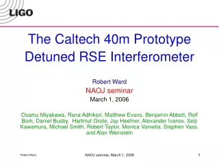
Optical spring and optical resonance in the 40m Detuned RSE interferometer LIGO seminar November 1, 2005

E N D
Optical spring and optical resonance in the 40m Detuned RSE interferometer LIGO seminar November 1, 2005 Osamu Miyakawa, Robert Ward, Rana Adhikari, Matthew Evans, Benjamin Abbott, Rolf Bork, Daniel Busby, Hartmut Grote, Jay Heefner, Alexander Ivanov, Seiji Kawamura, Michael Smith, Robert Taylor, Monica Varvella, Stephen Vass, and Alan Weinstein LIGO seminar, November 2005
Today’s talk • Advanced optical configuration • Caltech 40m prototype • Lock acquisition of detuned RSE • Optical spring and optical resonance LIGO seminar, November 2005
1. Advanced optical configuration LIGO seminar, November 2005
Development of Michelson type interferometer as a gravitational wave detector • Gravitational wave detection using Michelson interferometer • Signal and power enhancement using Fabry-Perot cavity in each arm • Power enhancement using Power Recycling FP cavity FP cavity Laser BS FP cavity FP cavity PRM Laser BS LIGO seminar, November 2005
Advanced LIGO optical configuration • LIGO:Power recycled FPMI • Optical noise is limited by Standard Quantum Limit (SQL) • AdvLIGO:GW signal enhancement using Detuned RSE • Two dips by optical spring, optical resonance • Can overcome the SQL QND detector FP cavity Power PRM Laser FP cavity BS GW signal Detuning LIGO seminar, November 2005
Resonant Sideband Extraction andSignal Recycling • Resonant Sideband Extraction(RSE) • Anti-resonant carrier on SRC • High finesse arm cavities required • Low power recycling, or power recycling not required • Less thermal effect • Better for long arm based interferometer • Signal Recycling(SR) • Resonant carrier on SRC • Low finesse arm cavities, or arm cavities not required • High power recycling required, so-called dual recycling(DR) • Higher thermal effect • Better for short arm based interferometer AdLIGO LCGT LIGO VIRGO TAMA300 GEO600 LIGO seminar, November 2005
Historical review of Advanced interferometer configuration ~1986 Signal Recycling (Dual Recycling) [B.Meers] ~1998 Garching 30m [G.Heinzel] GEO600 Glassgow 10m ~2000 Tabletop with new control • Caltech(RSE)[J.Mason] • Florida(DR) • Australia(RSE)[D.Shaddock] ~1993 RSE • Idea [J.Mizuno] • Tabletop [G.Heinzel] ~2005 Caltech 40m • Suspended mass • DRSE+PR ~2013 AdLIGO(DRSE) LCGT(BRSE) ~2002 NAOJ 4m Susp. mass BRSE [O.Miyakawa] ~2004 NAOJ 4m Susp. mass DRSE [K.Somiya] ~2001 QND study[Y.Chen, A. Buonanno] • Optical spring • Readout scheme LIGO seminar, November 2005
2. Caltech 40m prototype LIGO seminar, November 2005
Caltech 40 meter prototype interferometer An interferometer as close as possible to the Advanced LIGO optical configuration and control system • Detuned Resonant Sideband Extraction(DRSE) • Power Recycling • Suspended mass • Digital controls system LIGO seminar, November 2005
Caltech 40 meter prototype interferometer Objectives • Develop a lock acquisition procedure for suspended-mass detuned RSE interferometer with power recycling • Verify optical spring and optical resonance • Characterize noise mechanisms • Develop DC readout scheme • Extrapolate to AdLIGO via simulation BS SRM PRM Bright port Dark port X arm Y arm LIGO seminar, November 2005
Optical spring Optical spring in detuned RSE was predicted using two-photon mode. h a :input vacuum b :output D :input carrier M :constant h :gravitational wave hSQL:standard quantum limit t: transmissivity of SRM k: coupling constant F: GW sideband phase shift in SRC b: GW sideband phase shift in IFO arm cavity h Beam splitter D arm cavity laser Signal recycling mirror b a z: homodyne phase A. Buonanno, Y.Chen, Phys. Rev. D 64, 042006 (2001) LIGO seminar, November 2005
Standard Quantum Limit Target sensitivity of AdvLIGO and 40m prototype 2 dips, optical spring and optical resonance in detuned RSE LIGO seminar, November 2005
Differences betweenAdvLIGO and 40m prototype • 100 times shorter cavity length • Arm cavity finesse at 40m chosen to be = to AdvLIGO ( = 1235 ) • Storage time is x100 shorter • Control RF sidebands are 33/166 MHz instead of 9/180 MHz • Due to shorter PRC length, less signal separation • LIGO-I 10-watt laser, negligible thermal effects • 180W laser will be used in AdvLIGO. • Noisier seismic environment in town, smaller isolation stacks • ~1x10⁻⁶m at 1Hz • LIGO-I single pendulum suspensions • AdvLIGO will use triple (MC, BS, PRM, SRM) and quad (ITMs, ETMs) suspensions. LIGO seminar, November 2005
Carrier (Resonant on arms) -f2 -f1 f1 f2 AdLIGO signal extraction scheme ETMy • Mach-Zehnder will be installed to eliminate sidebands of sidebands. • Only + f2is resonant on SRC. • Unbalanced sidebands of +/-f2 due to detuned SRC produce good error signal for Central part. • Arm cavity signals are extracted from beat between carrier and f1 or f2. • Central part (Michelson, PRC, SRC) signals are extracted from beat between f1 and f2, not including arm cavity information. 4km f2 ITMy ETMx PRM ITMx BS 4km f1 SRM Single demodulation Arm information Double demodulation Central part information LIGO seminar, November 2005
Double Demodulation • Double Demodulation used for l+, l-, and ls • Demodulation phases optimized to suppress DC and to maximize desired signal Locking point Demodulation Phase of f2 LIGO seminar, November 2005
5 DOF for length control Signal Extraction Matrix (in-lock) ETMy Phase Modulation f1=33MHz f2=166MHz Ly=38.55m Finesse=1235 ITMy Common of arms Differential of arms Power recycling cavity Michelson Signal recycling cavity : L=(Lx Ly) / 2 : L=Lx Ly : l=(lx ly) / 2 =2.257m : l=lx ly = 0.451m : ls=( lsx lsy) / 2 =2.15m lsy ETMx PRM Laser ly ITMx BS lx Lx =38.55m Finesse=1235 lsx SRM PO SP AP LIGO seminar, November 2005
Carrier -f2 -f1 f1 f2 Disturbance by sidebands of sidebands Original concept Real world • Sidebands of sidebands are produced by two series EOMs. • Beats between carrier and f2 +/-f1 disturb central part. Carrier -f2 -f1 f1=33MHz f2=166MHz 199MHz 133MHz LIGO seminar, November 2005
EOM1 EOM2 Mach-Zehnder interferometer on 40m PSLto eliminate sidebands of sidebands Mach-Zehnder interferometer with no sidebands of sidebands Series EOMs with sidebands of sidebands PMC trans f2 PZT f1 f2 Locked by internal modulation EOM2 f1 To MC EOM1 PD PMC transmitted to MC LIGO seminar, November 2005
FSS MOPA126 PMC VCO AOM Pre-Stabilized Laser(PSL)and 13m Mode Cleaner(MC) BS East Arm • 10W MOPA126 • Frequency Stabilization Servo (FSS) • Pre-Mode Cleaner (PMC) • 13m Mode Cleaner ITMx ETMx ITMy PSL 40m arm cavity South Arm Mode Cleaner 13m MC Detection bench ETMy LIGO seminar, November 2005
Each optic has five OSEMs (magnet and coil assemblies), four on the back, one on the side The magnet occludes light from the LED, giving position Current through the coil creates a magnetic field, allowing mirror control LIGO-I type single suspension LIGO seminar, November 2005
Digital length control system D/A D/A AP166 A/D mixer Output to suspensions Feedback filters Demodulated signal from PD LIGO seminar, November 2005
Off-resonant lock scheme for arm cavity Transmitted light is used as to avoid coupling of carrier in PRC when arm cavity is locked. Resonant Lock Off-resonant Lock point LIGO seminar, November 2005
3. Lock acquisition of detuned RSE LIGO seminar, November 2005
ETMy Shutter ITMy PRM ETMx ITMx Carrier 33MHz 166MHz BS Shutter SRM The way to full RSE Oct. 2004 Detuned dual recycled Michelson Oct. 2005 RSE Nov. 2004 Arm lock with offset in common mode Reducing offset LIGO seminar, November 2005
DRMI lock using double demodulation with unbalanced sideband by detuned cavity Carrier Carrier 33MHz 166MHz ITMy ITMx BS Unbalanced 166MHz PRM DDM PD 33MHz Belongs to next carrier Belongs to next carrier SRM DDM PD OSA DDM PD OSA Typical lock acquisition time : ~1min Belongs to next carrier LIGO seminar, November 2005
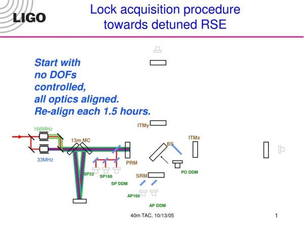
Lock acquisition procedure towards detuned RSE Low gain High gain Start TrY PDs POY ITMy 166MHz POX ITMx 13m MC High gain BS 33MHz PRM TrX PDs Low gain PO DDM SP33 SRM SP166 SP DDM AP166 AP DDM LIGO seminar, November 2005
Ly=38.55m Lx =38.55m T=7% T=7% Lock acquisition procedure towards detuned RSE Low gain High gain DRMI TrY PDs POY ITMy 166MHz POX ITMx 13m MC High gain BS 33MHz PRM TrX PDs Low gain PO DDM SP33 SRM SP166 I SP DDM Q AP166 AP DDM LIGO seminar, November 2005
Ly=38.55m Finesse=1235 1/sqrt(TrY) Lx =38.55m Finesse=1235 T=7% T=7% Lock acquisition procedure towards detuned RSE Normalization process Low gain High gain DRMI + 2arms with offset TrY PDs Typical lock acquisition time: 3minutes POY ITMy 166MHz POX ITMx 13m MC 1/sqrt(TrX) BS High gain 33MHz PRM TrX PDs Low gain PO DDM SRM SP166 SP33 I SP DDM Q AP166 AP DDM LIGO seminar, November 2005
Ly=38.55m Finesse=1235 1/sqrt(TrY) Lx =38.55m Finesse=1235 T=7% T=7% Lock acquisition procedure towards detuned RSE Normalization process Low gain High gain Switching DRMI to DDM TrY PDs POY ITMy 166MHz POX ITMx 13m MC 1/sqrt(TrX) BS High gain 33MHz PRM TrX PDs Low gain PO DDM SRM SP33 SP166 SP DDM AP166 AP DDM LIGO seminar, November 2005
-1 Ly=38.55m Finesse=1235 Lx =38.55m Finesse=1235 T=7% T=7% Lock acquisition procedure towards detuned RSE Normalization process Low gain High gain Switching to CARM and DARM control CARM: offset DARM: no offset 1/sqrt(TrX)+ 1/sqrt( TrY) TrY PDs (1/sqrt(TrX)- 1/sqrt( TrY)) (1/sqrt(TrX)+ 1/sqrt( TrY)) CARM + + POY DARM ITMy 166MHz POX ITMx 13m MC High gain BS 33MHz PRM TrX PDs Low gain PO DDM SRM SP33 SP166 SP DDM AP166 AP DDM LIGO seminar, November 2005
(POX+POY)/(TrX+TrY) + -1 + Ly=38.55m Finesse=1235 Lx =38.55m Finesse=1235 T=7% T=7% Lock acquisition procedure towards detuned RSE Normalization process Low gain High gain Switching CARM and DARM to RF CARM: offset DARM: no offset TrY PDs CARM + + POY DARM ITMy 166MHz POX ITMx 13m MC High gain BS 33MHz PRM TrX PDs Low gain PO DDM SRM SP33 SP166 SP DDM AP166 AP DDM AP166/(TrX+TrY) LIGO seminar, November 2005
(POX+POY)/(TrX+TrY) + -1 + Ly=38.55m Finesse=1235 GPR=14.5 Lx =38.55m Finesse=1235 T=7% T=7% Lock acquisition procedure towards detuned RSE Normalization process Low gain High gain TrY PDs Reduce CARM offset to Full RSE CARM + + DARM ITMy 166MHz POX ITMx ITMx 13m MC High gain BS 33MHz PRM TrX PDs Low gain PO DDM SRM SP33 SP166 SP DDM AP166 AP DDM AP166/(TrX+TrY) LIGO seminar, November 2005
-1 Ly=38.55m Finesse=1235 GPR=14.5 Lx =38.55m Finesse=1235 T=7% T=7% Lock acquisition procedure towards detuned RSE Low gain High gain TrY PDs CARM to MC and Laser frequency In Progress DARM POY ITMy 166MHz POX ITMx 13m MC High gain BS SP166 33MHz PRM TrX PDs Low gain PO DDM SRM SP33 SP DDM AP166 AP DDM LIGO seminar, November 2005
Dynamic compensative filterfor CARM servo by Rob Ward Optical gain of CARM Open loop TF of CARM Optical gain (normalized by transmitted power) shows moving peaks due to reducing CARM offset. We have a dynamic compensative filter having an exactly the same shape as optical gain except for upside down. Open loop transfer function has no phase delay in all CARM offset. LIGO seminar, November 2005
Residual displacement noise on arm Requirement of RMS noise for full lock (10% of FWHM of RSE) Requirement of RMS noise for offset lock (10% of FWHM of offset lock on CARM) RMS residual displacement noise was 30 times larger than requirement. Probably 30% of FWHM is OK. But still 10 times noisier. LIGO seminar, November 2005
Requirement of RMS noise for full lock (10% of FWHM of RSE) Noise investigation in DRMI+single arm LIGO seminar, November 2005
Lock acquisition for DRMI+2arms Maximum power Trial of re-alignment Lost lock Lock lasts 1-2hours Lock acquisition time 5-10minutes Drift exists by alignment, offset, or thermal effect. Start reducing offset 5DOF locked LIGO seminar, November 2005
4. Optical spring and optical resonance LIGO seminar, November 2005
L- optical gain with RSE peak Measured in June 2005 • Optical gain of L- loop DARM_IN1/DARM_OUT,divided by pendulum transfer function • No offset on L- loop • 150pm offset on L+ loop • Optical resonance of detuned RSE can be seen around the design RSE peak of 4kHz. • Q of this peak is about 6. Design RSE peak ~ 4kHz LIGO seminar, November 2005
Fdet (=4kHz at 40m) FWHM fsig Sideband amplitude at output [a.u.] LSB USB Signal sideband frequency offset from carrier [Hz] Simple picture of optical resonance • Response between GW USB and GW LSB is different due to the detuned signal recycling cavity. • the resonance of the SR cavity and is maximally enhanced for fsig = fdet Carrier frequency LIGO seminar, November 2005
h arm cavity h Beam splitter D arm cavity laser Signal recycling mirror b a Mathematical description for optical spring in detuned RSE a :input vacuum b :output D :input carrier M :constant h :gravitational wave hSQL:standard quantum limit t: transmissivity of SRM k: coupling constant F: GW sideband phase shift in SRC b: GW sideband phase shift in IFO Measurement of optical transfer function a<<h; non-quantum measurement LIGO seminar, November 2005
Simple picture of optical spring in detuned RSE Let’s move arm differentially, X arm longer, Y arm shorter from full RSE Wrong SRM position Correct SRM position BRSE X arm Y arm Y arm X arm Power(W) Power(W) Power(W) DARM (Lx-Ly) DARM (Lx-Ly) DARM (Lx-Ly) • Power X arm down, Y arm up X arm down, Y arm down X arm up, Y arm down • Radiation pressure X arm down, Y arm up X arm down, Y arm down X arm up, Y arm down • Spring constant Negative(optical spring) N/A Positive(no optical spring) LIGO seminar, November 2005
Optical spring and Optical resonance in differential arm mode of detuned RSE • Optical gain of L- loop DARM_IN1/DARM_OUT divided by pendulum transfer function • Optical spring and optical resonance of detuned RSE were measured. • Frequency of optical spring depends on cavity power, mass, detuning phase of SRC. • Frequency of optical resonance depends on detuning phase of SRC. • Theoretical line was calculated using A. Buonanno and Y.Chen’s equations. LIGO seminar, November 2005
Positive spring constant SRM is locked at opposite position from anti-resonant carrier point(BRSE). Optical spring disappeared due to positive spring constant. Broadband SR Broadband RSE LIGO seminar, November 2005
Frequency sweep of optical spring ~1900W ~270W LIGO seminar, November 2005
Optical spring in E2E Calculated by time domain simulation No length control Lock lasts ~0.7sec, so statistics at low frequency is not good. Simple length control required Calculation time ~5min using DRMI summation cavity LIGO seminar, November 2005
How much power inside arm? Design Measured(estimated) Cavity reflectivity 93% 85%(X arm 84%, Yarm 86%) PRM reflectivity 93% 92.2% Loss in PRC 0% 2.3% Achievable PRG 14.5 5.0 Coupling Over coupled Under coupled Input power 0.1W 1W Power in one arm 560W1900W Optical spring 23Hz 41Hz LIGO seminar, November 2005
CARM optical spring LIGO seminar, November 2005
Mode healing at Dark Port? Negative spring constant with optical spring Positive spring constant with no optical spring Repeatable The same alignment quality Under investigation. LIGO seminar, November 2005
Next step • Stable operation and noise hunting • E2E simulation for AdLIGO • DC readout • Squeezer • Alignment control with wave front sensors • Cleaning arms • Narrow-band operation • LF RF modulation scheme • Etc. LIGO seminar, November 2005