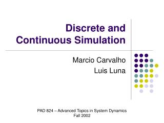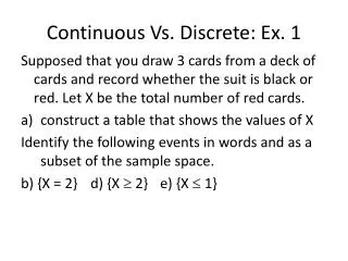
Continuous vs. Discrete
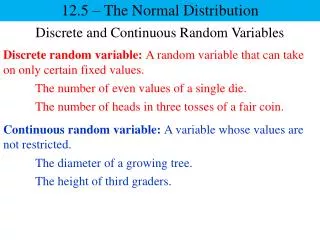
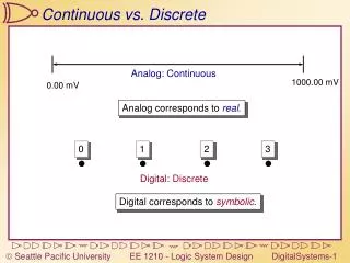
Analog: Continuous. 1000.00 mV. 0.00 mV. 2. 3. 0. 1. Continuous vs. Discrete. Analog corresponds to real. Digital: Discrete. Digital corresponds to symbolic. From Analog to Digital. 2. 3. 0. 1. 625. 875. 125. 375. 500.00. 750.00. 1000.00 mV. 0.00 mV. 250.00.

Continuous vs. Discrete
E N D
Presentation Transcript
Analog: Continuous 1000.00 mV 0.00 mV 2 3 0 1 Continuous vs. Discrete Analog corresponds to real. Digital: Discrete Digital corresponds to symbolic.
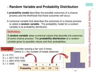
From Analog to Digital 2 3 0 1 625 875 125 375 500.00 750.00 1000.00 mV 0.00 mV 250.00 • Our analog signal had an infinite range of values in between 0.00 mV and 1000.00 mV • The new digital signal has only four values: 0,1,2,3 • ‘0’ corresponds to all values from 0 mV to 250 mV, but is represented by the value 125 mV • Likewise for 1,2, and 3
Digital Analog Sent Received Becomes 125 131.2 125 625 614.5 625375 347.3 375875 880.5 875 125 125.1 125 Sent Received 150 156.2624 613.5429 401.3987 992.1223 223.1 The issue of Noise 625 875 125 375 750.00 1000.00 mV 0.00 mV 250.00 500.00 Noise Margin - The amount of noise that can be added to a digitalsignal without changing the result. (Above example: +/- 125mV)
Finite representation 625 875 125 375 750.00 1000.00 mV 0.00 mV 250.00 500.00 Analog signal 1000 750 mV 500 Digital signal 250 0 time
Tradeoffs • Digital signals are limited (finite) - Analog signals are continuous (infinite) • We can always make the analog-to-digital conversion finer-grained • Analog signalsare very susceptible to noise - Digital signals can tolerate noise • The finer-grained the analog-to-digital conversion is, the smaller the noise margins • Noise beyond the noise margins does really bad things to digital signals
Other reasons for using Digital Systems • Computers use digital logic • Computers must be spoken to in their own language - digital systems are the way to go • Digital systems are easier to understand • Functions are defined by easy-to-understand binary logic instead of complex differential equations
Binary systems have two values Zero and One Binary numbers are easy to represent using physical phenomena All numbers can be represented in binary as well as in any other base Zero One ‘0’ ‘1’ False True Off On Low V High V 0 V 5 V Current No Current Binary Systems
H L Time 100% 90% 50% 10% 0% Waveforms Digital data can vary over time, making a digital waveform Rising Edge Falling Edge A Real Waveform Rise Time Fall Time
Clocks Regular Periodic waveforms are called Clock Signals Period TH TL Period is measured in seconds Frequency = 1/Period, measured in Hertz Example: TH = 3ns, TL = 2ns. What are period and frequency? Period = TH+TL = 5ns Frequency = 1/5ns = 200MHz
1 0 0 1 0 1 1 0 Using a Clock Consider this waveform, carrying digital data: What data does it carry? 101010? Apply a clock to it to understand the waveform. Sample it at each falling edge: 10010110 Warning: The sample clock must be the same frequency as the clock that was used to generate the waveform If the second clock was used, we’d have 1100001100111100
A B C F 1 1 1 1 A 0 1 1 0 1 0 1 0 B 0 0 1 1 1 1 0 0 C 0 1 0 1 1 0 0 1 F 0 0 0 1 Timing Diagrams A binary function, F(A,B,C), shown as a timing diagram Note: This “timing” diagram doesn’t have a time scale – we’ll get to that later
Number Systems Decimal 123410 = 1 x 10³ + 2 x 10² + 3 x 101 + 4 x 100 10102 = 1 x 23 + 0 x 22 + 1 x 21 + 0 x 20 = 1 x 8 + 0 x 4 + 1 x 2 + 0 x 1 = 810 + 210 = 1010 Binary General formula for convertingan n-digit number from base Bto decimal (Pi is the ith digit of the number)
Binary: Base 2 Decimal: Base 10 Hexadecimal: Base 16 It takes 4 binary digits (bits) to represent the numbers 0-15 Each group of 4 binary digits corresponds to exactly one hex digit Binary numbers Decimal BinaryHexadecimal 0 00000 1 00011 2 00102 3 00113 4 01004 5 01015 6 01106 7 01117 8 10008 9 10019 10 1010A 11 1011B 12 1100C 13 1101D 14 1110E 15 1111F
26 25 24 23 22 21 20 Binary-to-Decimal Conversion 20 1 21 2 22 4 23 8 24 16 25 32 26 64 27 128 28 256 29 512 210 1024 1K 211 2048 2K 212 4096 4K 213 8192 8K 214 16384 16K 215 32768 32K 216 65536 64K Each bit in a binary number refers to a power of two: 1 0 1 0 0 1 1 64+0+16+0+0+2+1 = 83
Decimal-to-Binary Conversion Start with decimal number N: 25 RepeatedSubtraction or sum-of weights method Subtract largest power of two £ N 25 - 24 = 25 - 16 = 9 Subtract largest power of two £ remainder = 9 9 - 23 = 9 - 8 = 1 Subtract largest power of two £ remainder = 1 22=4 is too large - skip Subtract largest power of two £ remainder = 1 21=2 is too large - skip Subtract largest power of two £ remainder = 1 1 - 20 = 1 - 1 = 0 Now, we see 2510 = 24 + 23 + 20 = 1 1 0 0 12