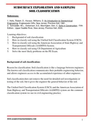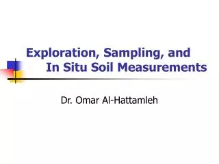
Soil Exploration
Lecture-5. Soil Exploration. Dr. Attaullah Shah. Today’s Lecture. Purpose of Soil Exploration Different methods Test trenches and Pits Auger and Wash Boring Rotary Drilling Geophysical Methods Soil Sampling (Disturbed and Undisturbed). COMMON STAGES IN SITE INVESTIGATION. Desk Study


Soil Exploration
E N D
Presentation Transcript
Lecture-5 Soil Exploration Dr. Attaullah Shah
Today’s Lecture Purpose of Soil Exploration Different methods Test trenches and Pits Auger and Wash Boring Rotary Drilling Geophysical Methods Soil Sampling (Disturbed and Undisturbed)
COMMON STAGES IN SITE INVESTIGATION Desk Study Site Reconnaissance Field Investigations a) Preliminary Ground Investigation b) Detailed Ground Investigation Laboratory Testing Report Writing Follow up Investigations during design & construction Appraisal of performance
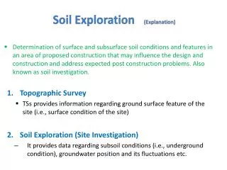
SOIL INVESTIGATION Determination of surface and subsurface soil conditions and features in an area of proposed construction that may influence the design and construction and address expected post construction problems. SCOPE OF INVESTIGATION • Simple visual examination of soil at the surface or from shallow test pits. • Detailed study of soil and groundwater to a reasonable depth (influence zone) by sampling from bore holes, shafts and audits and in-situ and laboratory tests.
PURPOSE OF SOIL INVESTIGATION: • The site investigation provides first hand information for; • Selection of foundation type. • Design of foundations. • Contractors to quote realistic and competitive tenders. • Planning construction techniques. • Selection of appropriate construction equipment (especially for excavation and foundations). • Feasibility studies of the site. • Estimating development cost for the site. • Study of environmental impacts of the proposed construction.
Selection of borrow areas for embankments. Need for any suitable soil improvements. Requirement of any surface or subsurface drainage. Selection of the most suitable and economical route for highways with respect to soil conditions. Selecting areas (better soil) for engineering structures where there is flexibility in relocating the structure thus realizing considerable savings in foundation costs. The design of extension works to existing structures. the investigation of the cases where failure has occurred, to know the causes and design of remedial works. PURPOSE OF SOIL INVESTIGATION: 6
METHODS OF INVESTIGATION The methods to determine the sequence, thickness and lateral extent of the soil strata and, where appropriate the level of bedrock. The common methods include Test pits Shafts and audits Boring or drilling
Test Pits The excavation of test pits is a simple and reliable method. The depth is limited to 4-5m only. The in-situ conditions are examined visually It is easy to obtain disturbed and undisturbed samples Block samples can be cut by hand tools and tube samples can be taken from the bottom of the pit.
1 2 3 4 Walls of the test pit indicate four layers (1) Clayey silt (2) Sandy silt (3) Clean sand (4) Sandy gravel 12
Boring or Drilling Boring refers to advancing a hole in the ground. Boring is required for the following: To obtain representative soil and rock samples for laboratory tests. To identify the groundwater conditions. Performance of in-situ tests to assess appropriate soil characteristics. Some of the common types of boring are as follows Auger boring Wash boring Percussion boring Rotary drilling
Auger Boring Hand Auger It is the simplest method of boring used for small projects in soft cohesive soils. For hard soil and soil containing gravels boring with hand auger becomes difficult. Hand-augered holes can be made upto about 20m depth, although depth greater than about 8-10m is usually not practical. The length of the auger blade varies from 0.3-0.5m. The auger is rotated until it is full of soil, then it is withdrawn to remove the soil and the soil type present at various depths is noted. Repeated with drawl of auger for soil removal makes boring difficult below 8-10m depth. The soil samples collected in this manner are disturbed samples and can be used for classification test. Auger boring may not be possible in very soft clay or coarse sand because the hole tends to collapse when auger is removed Hand Auger Mechanical Auger 14
Helical (worm types) Augers b. Short flight Auger c. Iwan (posthole) Auger a b c
Mechanical Auger Mechanical Auger means power operated augers. The power required to rotate the auger depends on the type and size of auger and the type of soil. Downwards pressure can be applied hydraulically, mechanically or by dead weight a a b c d a. Continuous Flight Auger b. Hallow-stem auger plugged during advancing bore c. Plug removed and sampler inserted d. Truck mounted auger boring machine
The diameter of the flight auger usually is between 75 to 300mm, although diameters up to 1m and bucket augers up to2m are available. Borehole depths up to 50m are possible with continuous-flight augers. The most common method is to use continuous flight augers. Continuous flight augers can be solid stem or hollow stem with internal diameter of 75-150mm. Hollow stem augers are used when undisturbed samples are required. Plug is withdrawn and sampler is lowered down and driven in to the soil below the auger. If bed rock is reached drilling can also take place through the hollow stem. As the auger acts as a casing it can be used in sand below water table. The possibility of rising sand in to the stem by hydrostatic pressure can be avoided by filling the stem with water up to the water table 17
The soil rises to the surface along the helical blades, obviating the necessity of withdrawal. • They are not suitable for soil bore that require casing, which demand removal of auger for driving the casing. • The presence of cobbles and boulders create problems with small-sized augers. • There is a possibility that different soil types may become mixed as they rise to the surface and it may be difficult to determine the depths of changes of strata. Experienced driller can however detect the change of strata by the change of speed and the sound of drilling.
Wash boring Water with high pressure pumped through hallow boring rods is released from narrow holes in a chisel attach to the lower end of the rods. The soil is loosened and broken by the water jet and the up-down moment of the chisel. The soil particles are carried in suspension to the surface between the rock and the borehole sites. The rods are raised and drop for chopping action of the chisel by means of winch. Wash boring can be used in most type of soil but the progress is slow in coarse gravel strata. 19
The accurate identification of soil strata is difficult due to mixing of the material has they are carried to the surface. • The method is unacceptable for obtaining soil samples. • It is only used for advancing the borehole to enable tube sample to be taken or field test to be carried at the hole bottom. • The advantage is that the soil immediately below the hole remains relatively un-disturbed
ROTARY DRILLING The rig consists of a derrick, power unit, winch, pump and a drill head to apply high-speed rotary drive and downward thrust to the drilling rods. Primarily intended for investigation in rock, but also used in soils. The drilling tool, (cutting bit or a coring bit) is attached to the lower end of hollow drilling rods The coring bit is fixed to the lower end of a core Water or drilling fluid is pumped down the hollow rods and passes under pressure through narrow holes in the bit or barrel The drilling fluid cools and lubricates the drilling tool and carries the loose debris to the surface between the rods and the side of the hole.
The fluid (bentonite slurry) also provides some support to the sides of the hole if no casing is used . • There are two forms of rotary drilling, open-hole drilling and core drilling. • Open- hole drilling, which is generally used in soils and weak rock, just for advancing the hole • The drilling rods can then be removed to allow tube samples to be taken or in-situ tests to be carried out. • In core drilling, which is used in rocks and hard clays, the diamond or tungsten carbide bit cuts an annular hole in the material and an intact core enters the barrel, to be removed as a sample. Typical core diameters are 41, 54 and 76mm, but can range up to 165 mm.
Advantages The advantage of rotary drilling in soils is that progress is much faster than with other investigation methods and disturbance of the soil below the borehole is slight. Limitations The method is not suitable if the soil contains a high percentage of gravel/cobbles, as they tend to rotate beneath the bit and are not broken up. The natural water content of the material is liable to be increased due to contact with the drilling fluid
GEOPHYSICAL METHOD Although boring and test pits provide definite results but they are time consuming and expensive. Subsurface conditions are known only at the bore or test pit location. The subsurface conditions between the boring need to be interpolated or estimated. Geophysical methods are more quick and cheaper. They provide thorough coverage of the entire area. The results of Geophysical testing however are less definitive and require subjective interpretation. Therefore both methods are important. In case geophysical testing in major in scope, few borings and sampling will be required for accurate determination of soil properties. If boring is major in scope then few geophysical lines will be required to know the conditions in-between the borings.
Site Evaluation Direct Methods Boreholes/Probes Test Pits/Trenches Cores 27
Geophysical Techniques Indirect Methods Ground Penetrating Radar (GPR) Electromagnetic (EM) Magnetic Utility Locating Seismic Electrical Resistivity Gravity Very Low Frequency (VLF)
Geophysical Techniques Indirect Methods Advantages Non-Destructive Cost Effective Provides Preliminary or Supplemental Information 29
Soil Sampling Split Spoon/SPT sampler Thin-wall tube/Shelby tube Augers
Soil Sampling Disturbed In situ structure not retained Water content, classification, compaction Undisturbed Less disturbed Shear strength, consolidation, permeability
Soil Sampling Disturbances Shearing and compression In situ stress release Drying Vibrations
How do we Sample Soil? Is it just digging holes?
Amount of sampling Depends upon; Time constraints Topography Cost factors Reasons for sampling There are no specific guidelines 34 Soil Analysis Ch 8
Soil Sampling How many samples do we take? At least 20 single samples per 10 000m2 must be taken with an earth boring tool (or spade) and combined to a mixed sample. To what depth do we sample? The usual sampling depth is up to 20 cm in arable land or 10cm in pasture. Undisturbed soil samples are obtained with a cutting cylinder with minimum capacity of 100cm3 . 35
GROUND INVESTIGATION TESTINGSelection of Testingfor SPECIFIERS
Laboratory Testing Testing by a laboratory accredited to ISO 17025 is an essential part of soil and rock testing • Competency of staff • Control of test conditions • Accuracy of test measurements • Traceability of measurements to national standards • Control of test material • Repeatability of results
Laboratory Testing • Soil and Water testing • Rock Testing • Chemical Testing (for effect on construction materials) • Contamination (Analytical) Testing
Types of Laboratory Tests • Classification tests • Chemical Tests • Compaction Tests • Shear strength and triaxial tests • Consolidation Tests • Permeability Tests • Specialist Tests • Rock Tests • Contamination Tests
Structuring the Test Schedule • Design data required and for what purpose • Identification of material characteristics • Identification of contamination levels • Type of sample needed • Minimum mass of sample • Multiple tests on samples 40
Classification Tests • Moisture content • Density • Atterberg limits • Particle size distribution 41
Rock Testing • Classification (moisture, density, porosity, slake durability) • Point load strength • Uniaxial compressive strength and modulus • Triaxial strength • Permeability 42
Chemical Tests • To provide design parameters for civil engineering materials in the ground • pH, sulphate, chloride, carbonate • Organic content and mass loss on ignition • Special testing (eg SD1) 43
Compaction Tests • Density/moisture content relationships • California bearing ratio (CBR) • Moisture condition value tests (MCV) • Maximum/minimum density • Combined relationship testing 44
Shear Strength and Triaxial Tests • Shear Box • Laboratory vane shear • Quick undrained triaxial test (total stress) • Consolidated undrained triaxial test (effective stress) • Consolidated drained triaxial test (effective stress) • Ring shear for residual strength 45
Consolidation Tests • One dimensional consolidation • Triaxial consolidation • Hydraulic cells (Rowe) • Swelling tests 46
Permeability Tests • Constant head permeameter • Falling head permeameter • Triaxial permeability
Contamination Testing • pH • Organics • Inorganics • Metals • Asbestos