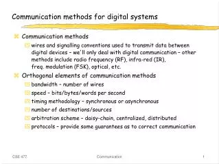
Communication methods for digital systems
Communication methods for digital systems. Communication methods wires and signalling conventions used to transmit data between digital devices – we'll only deal with digital communication – other methods include radio frequency (RF), infra-red (IR), freq. modulation (FSK), optical, etc.

Communication methods for digital systems
E N D
Presentation Transcript
Communication methods for digital systems • Communication methods • wires and signalling conventions used to transmit data between digital devices – we'll only deal with digital communication – other methods include radio frequency (RF), infra-red (IR), freq. modulation (FSK), optical, etc. • Orthogonal elements of communication methods • bandwidth – number of wires • speed – bits/bytes/words per second • timing methodology – synchronous or asynchronous • number of destinations/sources • arbitration scheme – daisy-chain, centralized, distributed • protocols – provide some guarantees as to correct communication Communication
Bandwidth • Serial • single wire to trasmit information one bit at a time • requires synchronization between sender and receiver • sometimes includes extra wires for clock and/or handshaking • good for inexpensive connections (e.g., terminals) • good for long-distance connections (e.g., LANs) • examples: RS-232, Ethernet, Apple desktop bus (ADB), Philips inter-integrated circuit bus (I2C), USB, Firewire, IrDA • Parallel • multiple wires to transmit information one byte or word at a time • good for high-bandwidth requirements (CPU to disk) • more expensive wiring/connectors/current requirements • examples: SCSI, PCI bus (PC), NuBus (Mac), PCMCIA Communication
Bandwidth • Issues • encoding • data transfer rates • cost of connectors and wires • modularity • error detection and/or correction Communication
Speed • Serial • low-speed, cheap connections • RS-232 1K–100Kbits/sec, copper wire • medium-speed efficient connections • I2C 10K-400Kbits/sec, board traces - IrDA 9.6K-4Mbits/sec, line-of-sight, .5m • high-speed, expensive connections • Ethernet 1.5-100Mbits/sec, twisted-pair or co-axial • Firewire 1+Gbit/sec • Parallel • low-speed, not too wide • SCSI bus, 10Mbytes/sec, 8 bits wide • NuBus, 40Mbytes/sec, 32 bits wide • PCI bus, 250Mbytes/sec, 32 bits wide • high-speed, very wide – memory systems in large multi-processors • 200M-2Gbytes/sec, 128-256 bits wide Communication
Speed • Issues • length of the wires (attenuation, noise, capacitance) • connectors (conductors and/or transducers) • environment (RF/IR interference, noise) • current switching (spikes on supply voltages) • number and types of wires (cost of connectors, cross-talk) • flow-control (if communicating device can’t keep up) Communication
Timing methodology • Asynchronous • less wires (no clock) • no skew concerns • synchronization overhead • appropriate for loosely-coupled systems (CPU and peripherals) • common in serial schemes • Synchronous • clock wires and skew concerns • no synchronization overhead • can be high-speed if delays are small and can be controlled • appropriate for tightly-couple systems (CPU and memory/disk) • common in parallel schemes Communication
Timing methodology • Issues • clock period and wire delay • synchronization and skew • encoding of timing and data information • handshaking • flow-control • power consumption Communication
Number of devices communicating • Single source – single destination • point-to-point • cheap connections, no tri-stating necessary • Single source – multiple destination • fanout limitations • addressing scheme to direct data to one destination • Multiple source – multiple destination • arbitration between senders • tri-stating capability is necessary • collision detection • addressing scheme • priority scheme • fairness considerations Communication
Arbitration schemes • Daisy-chain or token passing • devices either act or pass to next • fixed priority order • as many wires as devices • fairness issues • Centralized • request to central arbiter • central arbiter implements priority scheme • wires from/to each device can be costly • can be dynamically changing priority/fairness • Distributed • no central arbiter • common set of wires (or ether) observed by all devices • fixed priority/fairness scheme Communication
Serial Communication Examples • Ethernet (popularized by Xerox) • most popular local area network protocol with distributed arbitration • different versions from 1.5Mbit/sec to 100Mbit/sec • IrDA (Infrared Data Association) • up to 115kbps wireless serial (Fast IrDA up to 4Mbs) • standard on all laptops and PDAs, but also in desktop equipment • Firewire • 1+Gbits/sec • consumer electronics (video cameras, TVs, audio, etc.) Communication
Parallel Communication Examples • NuBus (Texas Instruments) • parallel system bus used for PCs • backbone of Apple Macintosh • PCI Bus (Intel) • parallel system bus for modern PCs • 66MHz with 32-bit wide data • PCMCIA (PC Memory Card Int'l Association) • mostly memory-oriented bus for personal computer cards • supports hot insertion/removal Communication
Ethernet (Xerox local area network) • Local area network • up to 1024 stations • up to 2.8 km distance • 100Mbits/sec serially on shielded co-axial cable • 10+Mbits/sec on twisted pair of copper pair • Developed by Xerox in late 70s • still most common LAN right now • being displaced by ATM (can't handle video/audio rates or make required service guarantees) • Slower than point-to-point networks • High-level protocols to ensure reliable data transmission • CSMA-CD: carrier sense multiple access with collision detection Communication
Ethernet layered organization • Physical and data-link layers are our focus Client Layer Transport Layer Data-link Layer Physical Layer ToHost Host-specific Interface Data-link Controller Physical Channel Transmit and Receive Electrical Interface Serial Encode and Decode Ethernet Cable Data Encapsulation Link Management Ethernet Controller Board Transceiver serial data parallel data Communication
Serial data format • Manchester encoding • signal and clock on one wire (XORed together) • "0" = low-going transition • "1" = high-going transition • Extra transitions between 00 and 11 need to be filtered • preamble at beginning of data packet contains alternating 1s and 0s • allows receivers to get used to where important transitions should be and ignore extra ones (this is how synchronization is achieved) • preamble is 48 bits long: 10101. . . 01011 0 1 0 1 0 1 1 0 0 Communication
Ethernet packet • Packets size: 64 to 1518 bytes + 6 bytes of preamble preamble (6 bytes) destination address (6 bytes) source address (6 bytes) type (2 bytes) data (46-1500 bytes) checksum (4 bytes) compute from data Communication
Arbitration • Wait for line to be quiet for a while then transmit • detect collision • average value on wire should be exactly between 1 and 0 • if not, then two transmitters are trying to transmit data • If collision, stop transmitting • wait a random amount of time and try again • if collide again, pick a random numberfrom a larger range (2x) and try again • Exponential backoff on collision detection • Try up to 16 times before reporting failure Communication
Extending Ethernet • Segments, repeaters, and gateways • segment: a single cable • repeater: transfers all messages on one segmentto another and vice-versa • gateway: selectively forwards messages to another segmenthelps to isolate traffic Communication
NuBus (Texas Instruments and Apple) • Parallel system bus (within a computer) • used in TI and Apple computers • 40MBytes/sec maximum transfer rate • fully synchronous (data transfer and arbitration) • Supports up to 16 masters • distributed arbitration • fairness enforced • All operations are memory-mapped • read/write is everything • Mechanical standards • size and shape of boards • position of pins • capacitance limits Communication
NuBus organization • Up to 16 elements • masters originate operations • slaves respond to requestsfrom masters • slot ID provides partof addressing Utility reset, clock Control start, ack, tm0, tm1 Addr/Data ad[31:0] Arbitration arb[3:0], rqst Parity sp, spv Slot ID id[3:0] Power/Ground +5 (11), -5 (8), +12 (2), -12v (2), gnd (23)Total 96 pins 3 rows of 32 pins Slave Master Slave Master Slot ID Slot ID Slot ID Slot ID Data, Control, and Parity ClockGenerator Arbitration Clock Communication
Addressing • Multiplexed address/data bus • Slot ID provides second set of high-order 4 bits of address FFFFFFFF SLOT 15 slot space(1/16 of total)configuration registers(interrupts, address range, etc.) SLOT 0 F0000000 uncommitted space(15/16 of total)all other data 00000000 Communication
NuBus timing • 100ns cycle time, 75% duty cycle • allows more time for propagation of signals, less for skew period 25ns 75ns clk signal sampleedge assertionedge Communication
Data transactions • Read • Write CLK ADx/ DATA ADDRESS TMx/ MODE STATUS START ACK CLK ADx/ ADDRESS DATA TMx/ MODE STATUS START ACK Communication
Transfer modes and status codes • TM0/, TM1/, AD1/, AD0/ define transfer mode from master • TM0/, TM1/ define status code from slave TM1/ TM0 /AD1/ AD0/ Type of transfer0 0 0 0 write byte 30 0 0 1 write byte 20 0 1 0 write byte 10 0 1 1 write byte 0 0 1 0 0 write halfword 1 0 1 0 1 write block (2 to 16 words specified using AD2/ to AD5/ 0 1 1 0 write halfword 00 1 1 1 write word 1 0 0 0 read byte 31 0 0 1 read byte 21 0 1 0 read byte 11 0 1 1 read byte 0 1 1 0 0 read halfword 1 1 1 0 1 read block (2 to 16 words specified using AD2/ to AD5/ 1 1 1 0 read halfword 01 1 1 1 read word TM1/ TM0/ Type of acknowledge0 0 bus transfer complete0 1 error1 0 bus timeout error1 1 try again later Communication
Arbitration • Distributed arbitration • devices requesting bus place ID values on open-collector ARB lines • if value on ARB ID then they stop driving ARB lines • device with ARB ID gets bus (must be decided in 2 bus cycles) • e.g., #1 vs. #2: #1 #2 bus 0001 0010 0000 start arbitration 0... 0... 0... check 1st bit (both ok) 00... 00... 00... check 2nd bit (both ok) 000... 001... 000... check 3rd bit (#2 loses and removes itself) 0001 ... 0001 check 4th bit (#1 matches and wins) Communication
Arbitration (cont’d) • Avoids starvation by doing arbitration in rounds • RQST/ must be high before device can request bus • all simultaneous requestors are taken care ofbefore others can request • bus is quiet after ACK/ and before next START/ • Fairness • all requestors in round are taken care of • master may monopolize the bus if it doesn't raise its RQST/ and • releases ARB/ lines – sometimes necessaryfor time critical actions Communication
Arbitration example transactionfor #2 transactionfor #1 transactionfor #15 ADR DATA ADR DATA DATA ADR #2 #1 #15 contest#1 vs. #2 contest#1 only contest#15 only because RQST/ is unasserted, #15 may assert it and contend #2 removes RQST/ and takes its ID off ARB lines #1 and #2 desire busand assert RQST/ and contend #1 releases RQST/ as it initiates transaction #15 desires bus but cannot contend because RQST/ is asserted Communication
Arbitration logic • ARB/ lines are open-collector • ID/ values are hard-wiredon each slot of NuBus chassis ARB/ GRANT ID3/ ARB3/ ID2/ ARB2/ ID1/ ARB1/ ID0/ ARB0/ Communication
PCMCIA/JEIDA (PC card) • Parallel bus for memories and I/O devices • under control of a single master processor (no arbitration) • 16-bit wide data transfers • 26-bit address space • Designed for portable applications • 3.3mm thick cards with 68-pin connectors (2 rows of 34 pins) • 5.0v or 3.3v operation • supports hot-insertion/removal • short power pins • medium length signal pins • long ground pins • Card types • PCMCIA type I: 3.3mm thick cards (requires QFP surface mount) • PCMCIA type II: 5mm (for cabling, e.g., FAX/modem) • PCMCIA type III: 10.5mm (for hard disks, wireless transceivers) insertion removal Communication
PCMCIA signals • For memory cards (SRAM, DRAM, Flash, ROM) • For I/O cards(disks, FAX/modem, wireless transceiver) • IREQ/ replaces BSY/ • IOR/ replaces OE/ • IOW/ replaces WE/ 25:0 15:0 OE/, WE/, WAIT/ CE1/, CE2/, RESET, REG/ CD1/, CD2/ BVD1, BVD2, WP, RDY or BSY/ Vcc, Vpp1, Vpp2, GND, VS1, VS2 Address Data Cycle Control Card Control Card Detect Status Power PC Card Communication
PCMCIA signals • Address/Data • 26 bits of address space, 16 bits parallel data (can also just use 8 bits) • Cycle Control • read (OE/), write (WE/), and wait (WAIT/) • Card Control • reset (RESET), access card information structure (REG/),low and high byte selects (CE1/, CE2/) • Card Detect • shortest pins at either end of connector to determine propercard insertion (CD1/, CD2/) • Status • card battery voltage detect and reset (BVD1, BVD2), write protected (WP), card ready (RDY or BSY/, used to slow down data transaction) • Power • power to card (Vcc, GND) • programming voltage for flash memory (Vpp1, Vpp2) • card voltage requirements (VS1, VS2) Communication
Data transactions • Asynchronous transfer • pace set by system using card • can be slowed down by the system using WAIT/ or by the card using RDY line • OE/ and WE/ determine read and write, respectively • CE1/ and CE2/ select width of transfer • REG/ is used to select reading of card information structure (CIS) Communication
PCMCIA architecture • Card information structure (CIS) • separate memory space for manufacturer information on card • also used as configuration space for card, e.g., modem baud rate • Layers of software make card usable by the system • socket services: reads CIS, configures card on behalf of card services, sends commands to card interface, forward interrupts (independent of specific cards) • card services: operating system component, performs resource allocation for applications, keeps track of insertion and removal of cards, uses socket service to interact with card (independent of specific cards) • card drivers: actually know how to use specific cards and use card services to execute operations Communication