Download
1 / 31
320 likes | 395 Vues
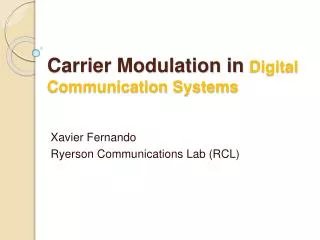
CHAPTER 6 PASS-BAND DATA TRANSMISSION. Digital Communication Systems 2012 R.Sokullu. 1 /31. Outline. 6.3 Coherent Phase Shift Keying - QPSK Offset QPSK π /4 – shifted QPSK M-ary PSK 6.4 Hybrid Amplitude/Phase Modulation Schemes M-ary Qudarature Amplitude Modulation (QAM).

E N D
CHAPTER 6PASS-BAND DATA TRANSMISSION Digital Communication Systems 2012 R.Sokullu 1/31
Outline • 6.3 Coherent Phase Shift Keying - QPSK • Offset QPSK • π/4 – shifted QPSK • M-ary PSK • 6.4 Hybrid Amplitude/Phase Modulation Schemes • M-ary Qudarature Amplitude Modulation (QAM) Digital Communication Systems 2012 R.Sokullu 2/31
Offset QPSK • In the example from the previous lecture we had the following time diagram for QPSK: Digital Communication Systems 2012 R.Sokullu 3/31
QPSK Equations: Digital Communication Systems 2012 R.Sokullu 4/31
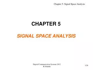
Figure 6.6Signal-space diagram of coherent QPSK system. Digital Communication Systems 2011 R.Sokullu 5/31
…translated to a space-signal diagram it looks like this: Figure 6.10 which shows all the possible paths for switching between the message points in (a) QPSK and (b) offset QPSK. Digital Communication Systems 2012 R.Sokullu 6/31
So, • we can make the following conclusions: • The carrier phase changes by ±180o whenever both the in-phase and the quadrature components of the QPSK signal change sign (01 to 10) • The carrier phase changes by ±90odegrees whenever the in-phase or quadrature component changes sign (10 to 00 – in-phase changes, quadrature doesn’t changes) • The carrier phase is unchanged when neither the in-phase nor the quadrature component change sign. (10 and then 10 again). Conclusion: Situation 1 is of concern when the QPSK signal is filtered during transmission because the 180 or also 90 degrees shifts in carrier phase might result in changes in amplitude (envelope of QPSK), which will cause symbol errors (for details see chapter 3 and 4 on envelope detection) Digital Communication Systems 2012 R.Sokullu 7/31
To overcome this problem a simple solution is proposed – delaying the quadrature component with half a symbol interval (i.e. offset) with respect to the bit stream responsible for the in-phase component. • So the two basis functions are defined as follows: Digital Communication Systems 2012 R.Sokullu 8/31
…translated to a space-signal diagram it looks like this: Figure 6.10 which shows all the possible paths for switching between the message points in (a) QPSK and (b) offset QPSK. Digital Communication Systems 2012 R.Sokullu 9/31
With this correction the possible phase transitions are limited to ±90o (see Fig.10b) • Changes in phase occur with half the intensity in offset QPSK but twice as often compared to QPSK • So, the amplitude fluctuations due to filtering in offset QPSK are smaller than in the case with QPSK • As for probability of error – it doesn’t change (based on the statistical independence of the in-phase and quadrature components) Digital Communication Systems 2012 R.Sokullu 10/31
Outline • 6.3 Coherent Phase Shift Keying - QPSK • Offset QPSK • π/4 – shifted QPSK • M-ary PSK • 6.4 Hybrid Amplitude/Phase Modulation Schemes • M-ary Qudarature Amplitude Modulation (QAM) Digital Communication Systems 2012 R.Sokullu 11/31
π/4-Shifted QPSK • Another variation of the QPSK modulation technique • In ordinary QPSK the signal may reside in anyof the following constellations: Figure 6.11 Digital Communication Systems 2012 R.Sokullu 12/31
π/4-Shifted QPSK – cont’d • In the so called π/4-shifted QPSK the carrier phase for the transmission of successive symbols is picked up alternatively from one of the two QPSK constellations – so eight possible states. • Possible transitions are give by dashed lines on the following figure. • Relationships between phase transitions and dibits in π/4-shifted QPSK are given in Table 6.2 Digital Communication Systems 2012 R.Sokullu 13/31
Figure 6.12 Digital Communication Systems 2012 R.Sokullu 14/31
Advantages of π/4-shfted QPSK: • The phase transitions from one symbol to another are limited to ±π/4 and ±3π/4 radians (compared to ±π/2 and ±π in QPSK) – significantly reduce amplitude fluctuations due to filtering. • π/4-shfted QPSK can be noncoherently detected which simplifies the receiver (offset QPSK cannot) • in π/4-shfted QPSK signals can be differentially encoded which creates differential π/4-shfted QPSK (DQPSK) Digital Communication Systems 2012 R.Sokullu 15/31
Generation of π/4-shfted DQPSK signals • Based on the symbol pair: In-phase component differentially encoded phase change for symbol k absolute phase angle of symbol k-1 Quadrature component absolute phase angle of symbol k Digital Communication Systems 2012 R.Sokullu 16/31
Example 6.2 We have a binary input 01101000 and a π/4- shifted DQPSK. Initial phase shift is π/4. Define the symbols Transmitted according to the convention in Table 6.2 (Formula 6.43 and 6.44) Digital Communication Systems 2012 R.Sokullu 17/31
Example 6.2 Digital Communication Systems 2012 R.Sokullu 18/31
Detection of π/4-shfted DQPSK • Assume that we have a noise channel (AWGN) and the channel output is x(t). • The receiver first computes the projections of x(t) onto the basis functions φ1(t) and φ2(t). • Resulting outputs are denoted by I and Q respectively and applied to a differential detector, which consists of the following components: • arctangent computing block (extracting phase angle) • phase difference computing block (determining change in phase) • Modulo-2π correction logic (wrapping errors) Digital Communication Systems 2012 R.Sokullu 19/31
Wrapping errors In this example θk-1 = 350o θk = 60o (measured counter clockwise) Actual Phase change = 70o but if calculated directly: 60o – 350o = 290o Correction is required. Digital Communication Systems 2012 R.Sokullu 20/31
Correction rule: • so, after applying the correction rule for the previous example we get: Δθk = -290o + 360o = 70o Digital Communication Systems 2012 R.Sokullu 21/31
Block diagram of the π/4-shfted DQPSK detector Figure 6.13 • Relatively simple to implement • Satisfactory performance in fading Rayleigh channel, static multipath environment • Not very good performance for time varying multipath environment Digital Communication Systems 2012 R.Sokullu 22/31
M-ary PSK • More general case than QPSK • Phase carrier takes one of M possible values, θi= 2(i-1)π/M, where i = 1,2,…M • During each signaling interval T one of M possible signals is sent: signal energy per symbol carrier frequency Digital Communication Systems 2012 R.Sokullu 23/31
s(t) may be expanded using the same basis functions defined for binary PSK – φ1(t) and φ2(t). • The signal constellation is two dimensional. • The M message points are equally spaced on a circle of radius and centered at the origin. • The Euclidian distance between each two points for M = 8 can be calculated as: Digital Communication Systems 2012 R.Sokullu 24/31
Figure 6.15(a) Signal-space diagram for octaphase-shift keying (i.e., M 8). The decision boundaries are shown as dashed lines. (b) Signal-space diagram illustrating the application of the union bound for octaphase-shift keying. Digital Communication Systems 2012 R.Sokullu 25/31
Symbol Error • Note: The signal constellation diagram is circularly symmetric. • Chapter 5: The conditional probability of error Pe(mi) is the same for all I, and is given by: Digital Communication Systems 2012 R.Sokullu 26/31
Using the above mentioned property and equation we calculate the average probability of symbol error for coherent M-ary PSK as: (M ≥ 4) • Note that M = 4 is the special case discussed before as QPSK. Digital Communication Systems 2012 R.Sokullu 27/31
Power spectra of M-ary PSK Signals • Symbol duration for M-ary PSK is defined as: • Proceeding in a similar manner as with QPSK and using the results from the introductory part of chapter 6 we can see that the baseband power spectral density of M-ary PSK is given by: Digital Communication Systems 2012 R.Sokullu 28/31
Figure 6.16Power spectra of M-ary PSK signals for M 2, 4, 8. OPSK QPSK BPSK BPSK Digital Communication Systems 2012 R.Sokullu 29/31
Bandwidth Efficiency of M-ary PSK Signals • From the previous slide of the power spectra of the M-ary PSK it is visible that we have a well defined main lobe and spectral nulls. • Main lobe provides a simple measure for the bandwidth of the M-ary PSK. (null-to-null bandwidth). • For the passband basis functions defined with (6.25) and (6.26) (which are required to pass the M-ary PSK signals) the channel bandwidth is given by: Digital Communication Systems 2012 R.Sokullu 30/31
Also, we have from before So we can express the bandwidth in terms of bit rate as: and the bandwidth efficiency as: Digital Communication Systems 2012 R.Sokullu 31/31