Download

1 / 211
2.46k likes | 3.11k Vues
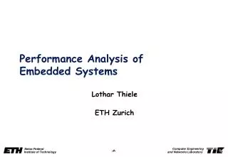
Performance Analysis of Digital communication Systems. DIGITAL COMMUNICATION. Block Diagram. Receiver. Digital message Source. Sink. Transmitter. Channel. Functional model of digital communication system : digital message. :Transmitted signal. : The channel noise.

E N D
Performance Analysis of Digital communication Systems DIGITAL COMMUNICATION
Block Diagram Receiver Digital message Source Sink Transmitter Channel Functional model of digital communication system • : digital message. • :Transmitted signal. • : The channel noise. • : The received signal. • : An estimate of the transmitted digital message.
Performance Measure (Figure of Merit): Waterfall shape • : i.e. The probability of error, it could be the Bit error Rate (BER) or Symbol Error Rate (SER). • : Energy per transmitted bit (Joule). • : Single sided PSD of White noise (Watt/Hz). • is dimensionless and equivalent to the
P(0/0) “0” “0” Probability of Error: P(1/0) P(0/1) • : Probability of receiving “0” given that “0” was transmitted which is probability of correct. • : Probability of receiving “1” given that “1” was transmitted which is probability of correct. • : Probability of receiving “1” given that “0” was transmitted which is probability of error. • : Probability of receiving “0” given that “1” was transmitted which is probability of error. Rx Tx “1” “1” P(1/1) Binary Symmetric Channel
Probability of Error (Cont.): • Probability of error ≡ Probability of Rx “0” given that “1” is Tx or vice versa • Pe = P(0) P(1/0) + P(1) P(0/1) • P(0) probability of sending “0”. • P(1) probability of sending “1”. • If P(0)=P(1) equally likely (equally probable). • Since the channel is symmetric
Channel Noise: • is a sample function of which is assume to be Wide-sense Stationary process (WSS) with zero mean and Power spectral density (PSD): . Also its distribution is assumed to be Gaussian. • is called Additive White Gaussian Noise (AWGN). • The cannel is called also AWGN channel. Receiver Digital message Source Sink Transmitter Channel
Gaussian Distribution: • (PDF) • (CDF)
G.D (Cont.) area • Where is the CDF for a zero mean, unity variance G.R.V. • Let Called the Q-function.
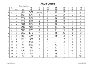
Q-tables • e.g.: Q(2.2)=?
G.D. (Cont.) Area 1 0.5
G.D. (Cont.) • The complementary error function is defined as: • erfc-function and the Q-function are related by:
Random Processes and LTI Systems: LTI system Output Input WSS
R.P. & LTI Systems (Cont.) • In our assumption the noise is Gaussian with , and , so the output from an LTI system is Gaussian with . • Since which is the average power of .
Thermal Noise in Communication Systems: • A natural noise source is thermal noise, who amplitude statistics are well modeled to be Gaussian with zero mean. • The autocorrelation and PSD are well modeled as: • Where k = 1.38 × 10⁻²³ (joule/Kelvin) is Boltzmann’s constant, G is conductance of the resistor (mhos); T is temperature in degrees Kelvin; and is the statistical average of time intervals between collisions of free electrons in the resistor (on the order of sec).
White Noise: • The noise PSD is approximately flat over the frequency range of 0 to 10 GHz ⇒ let the spectrum be flat from 0 to ∞: • Where is a constant. • Noise that has a uniform spectrum over the entire frequency range is referred to as white noise. • The autocorrelation of white noise is: • Since for , any two different samples of white noise, no matter how close in time they are taken, are uncorrelated. • Since the noise samples of white noise are uncorrelated, if the noise is both white and Gaussian (for example, thermal noise) then the noise samples are also independent.
Performance Analysis of Baseband System with Polar line Coding: p(t) Ap -p(t) “1” “0” Tp t t Tp To To - Ap “1” “1” “0” “1” s(t) Ap r(t) Tp To 2To 3To Decision Making Instants Ap+n<0 -Ap+n<0 Correct Decision Detection error - Ap 11011001
Rx Tx Channel Threshold Detector Decision Making Device Sampler Optimum Threshold Let +A N: Noise amplitude at the sampling instant R.V. -Ap N: Gaussian R.V. with zero mean and variance (n) # - Ap Ap /
Cont. P(error/1) = P(n < -Ap) = P(n > +Ap) = Q(Ap/) ) ) + ) Let Unipolar ?Bipolar ?
Pe can be minimized by maximizing (Ap/), this will be done by passing the digital signal through an optimum filter (called match filter). Filter h(t) Threshold Detector The filter will enhance the pulse amplitude & at the same time reduce the noise power () t t To tm=To 2To
Cont. After adding the filter we maximize
Cont. Using Schwarz inequality: The equality holds if Let Equality if: ; If p(t) is real =
Cont. (Unitless) Where Epis the energy of p(t) Match filter
p(t) tm < To Non causal t t tm To To tm > To tm = To • Min. delay for • decision making t t tm To=tm To
tm = To The optimum value The width of is 2To & symmetrical about To because: Multiplies both the signal and the noise • Does not affect = 1 Which is the energy
Alternative method to realize a match filter: Filter • But hopt(t) Threshold Detector
Cont. (Correlator) Integrate and dump Which is the time cross-correlation function. Threshold Detector Correlation Receiver :Correlator
Optimum linear receiver for a general binary system: Filter • Let us transmit “1” as and “0” as . h(t) Threshold Detector Decision Making device is the Optimum Threshold
Cont. • Let Which is a sampled version of is a G.R.V with zero mean & variance • Let since it is time independent. • is a G.R.V. with mean or depending on whether or “0” with variance .
Cont. • The Conditional PDFs of are:
Cont. Conditional PDFs y Equally likely
Cont. = =
Cont. • : Which is the arithmetic mean.
Cont. • To minimize we have to maximize .
Cont. • Using Schwarz inequality: where is an arbitrary constant.
Cont. • For AWGN • from Parseval’s theorem • , since
Cont. • Where: • . • .
Cont. • Hints:
Receiver design Threshold Detector Threshold Detector + + - - 0 0
Polar Signaling: • “1” • “0” • & • Since noise & signal are multiplied by the same ratio
Polar(Cont.) • is the average energy per bit. • ,
Polar(Cont.) • Average Transmitted power. 1 10 15 (dB)
Unipolar (On-Off signaling) • 1” • “0” • ,
Orthogonal Signals • Orthogonality: • , , • For baseband Binary: orthogonal signals are not better than Polar.
Signal Space Analysis: Receiver Digital message Source Sink Transmitter Channel • Message source emits one symbol every • Symbol belongs to an alphabet of M symbols • With a priori probabilities
Cont. • @ • @Rx: