Helium Ionization Detector
The Helium Ionization Detector is a universal detector, responding to all molecules except neon. It requires only helium carrier and make-up gas, and is sensitive to the low ppm range. For more information, please visit - http://quadrexcorp.com/<br>

Helium Ionization Detector
E N D
Presentation Transcript
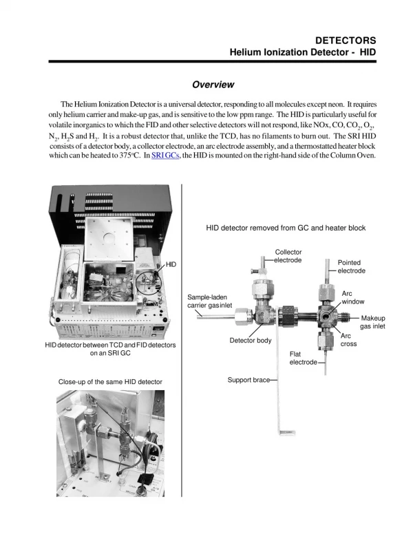
DETECTORS Helium Ionization Detector - HID Overview The Helium Ionization Detector is a universal detector, responding to all molecules except neon. It requires only helium carrier and make-up gas, and is sensitive to the low ppm range. The HID is particularly useful for volatile inorganics to which the FID and other selective detectors will not respond, like NOx, CO, CO2, O2, N2, H2S and H2. It is a robust detector that, unlike the TCD, has no filaments to burn out. The SRI HID consists of a detector body, a collector electrode, an arc electrode assembly, and a thermostatted heater block which can be heated to 375oC. In SRI GCs, the HID is mounted on the right-hand side of the Column Oven. HID detector removed from GC and heater block Collector electrode Pointed electrode HID Arc window Sample-laden carrier gas inlet Makeup gas inlet Arc cross Detector body HID detector between TCD and FID detectors on an SRI GC Flat electrode Support brace Close-up of the same HID detector
DETECTORS HID - Helium Ionization Detector Theory of Operation The SRI HID detector uses two electrodes which support a low current arc through the helium make-up gas flow. The helium molecules between the electrodes are elevated from ground state to form a helium plasma cloud. As the helium molecules collapse back to ground state, they give off a photon. The sample molecules are ionized when they collide with these photons. All compounds having an ionization potential lower than 17.7eV are ionized upon contact with photons from the helium cloud. The ionized component molecules are then attracted to a collector electrode, amplified, and output to the PeakSimple data system. Collector electrode Ground electrode Photons in the make-up gas stream Helium plasma cloud Sample-laden carrier flow Makeup gas flow Purple arc Ionization reaction: photons colliding with sample molecules Arc electrode NOTE: If the arc electrode is covered with TeflonTM (translucent) insulation, it should leave 1mm of its tip exposed. If the flat electrode is covered with ceramic (white) insulation, then the tip should be flush with the edge of the insulation sleeve. There should be a 1-2mm gap between the arc electrodes, and this gap should be centered in the arc cross.
DETECTORS Helium Ionization Detector - HID Expected Performance HID noise run Columns: 1m Mol. Sieve, 2m Hayesep-D Carrier: Helium @ 10mL/min HID gain = HIGH HID current = 70 HID temp = 200oC Temperature Program: Initial Hold 80oC 15.00 Ramp Final 0.00 80oC HID noise averages less than 100µV from peak to peak Test Analysis of 1cc 1000ppm C1-C6 Method: valve injection Column: 1m (3’) Silica Gel Carrier: Helium @ 10mL/min HID gain = HIGH HID temp = 150oC HID make-up = 29psi @ 40mL/min Temperature program: Initial Hold 50oC 1.00 10.00 220oC 10.00 Ramp Final 220oC 0.00 220oC Results: Component O2/N2 Methane Ethane Propane Butane Pentane Hexane Retention 0.766 1.066 3.550 8.083 12.850 16.950 20.800 total Area 3350.0970 1163.1965 2161.0940 3001.6200 3958.3250 4849.9755 5023.0105 23507.3185
DETECTORS HID - Helium Ionization Detector General Operating Procedure 1.Set the HID amplifier gain switch to HIGH for most applications from the ppm level to 1%. Use the MEDIUM gain setting for slightly more concentrated samples. 2.Set the helium make-up gas flow to 40mL/min, and the helium carrier gas flow to 10mL/min. The make-up gas flow is critical to the HID’s performance. With insufficient make-up flow, the chlorinated peaks will be inverted on the chromatogram; see the chromatograms compared on the HID Make-up Gas Flow page. Clean, high purity helium is best; moisture, air, and other contaminants can cause problems. 3.Set the HID temperature to 200oC. This temperature will help prevent moisture accumulation in the detector’s arc assembly. 4.Zero the data system signal, then switch ON the HID current; the switch is located on the GC’s front control panel under “DETECTORPARAMETERS.” Set the HID current at 100 using the trimpot setpoint on the top edge of the front control panel. 5.When the HID is OFF and the signal zeroed, and the HID is then turned ON, the milliVolt offset at HIGH gain setting should be 200-800mV. A higher offset means more sensitivity, but less dynamic range. If the offset is less than 200, the arc and ground electrodes are probably too close. 6.Observe the arc window; if you can see the purple arc between the ground and arc electrodes, proceed to step 7. If the arc goes sideways to the detector body instead of down to the ground electrode, then the gap between the electrodes is too large. If you cannot see the arc, A.Use a multimeter to check the voltage between the arc and ground electrodes. With the HID current at 100, the voltage reading should be greater than 200VDC (our readings average around 240VDC). B.Look through the arc window at the arc and ground electrodes. If they appear to be touching, disconnect the red electrode lead wire then check the continuity between the electrodes using a multimeter; the reading should be open or infinite. C.If the continuity between the electrodes is not open, re-gap the electrodes. 7.Let the milliVolt reading stabilize, then begin the analytical run.
DETECTORS Helium Ionization Detector - HID HID Make-up Gas Flow The following chromatograms were produced by an SRI HID equipped GC. Excepting the make-up gas flows, all run conditions are identical. The first chromatogram resulted from a make-up gas flow of 20mL/min. Drastically different in appearance from the first, the second chromatogram was produced with a make-up gas flow of 10mL/min. In the absence of sufficient make-up gas flow, the chlorinated peaks are negative. Not every HID has the same optimum make-up flow; experiment with different flow rates until you find the best range for your detector. Sample: 0.5mL 1000ppm C1-C6 Column: 30m MXT1-5 Carrier: Helium @ 10mL/min Temperature program: Initial Hold 50oC 1.00 Ramp Final 10.00 140oC Results: Component Solvent Benzene TCE Toluene PCE Ethyl Benzene 2.998 Bromoform Ortho Xylene Make-up: 20mL/min Retention 0.305 0.896 1.145 1.790 2.305 Area 4791.9566 14.5888 17.9614 19.6294 21.3786 23.5176 22.0414 26.3280 3.221 3.470 Total: 4937.4018 Results: Component Solvent Benzene TCE Toluene Ethyl Benzene 2.993 Ortho Xylene Make-up: 10mL/min Retention 0.381 0.876 1.266 1.771 Area 1771.5762 622.0096 527.2432 571.1129 379.2581 312.9010 3.468 Total: 4184.1010
DETECTORS HID - Helium Ionization Detector Cleaning the HID If your HID baseline seems noisy, try cleaning the electrodes following the steps below. Over time, the HID electrodes can develop a coating of soot, which can cause the arc to flicker or change position, resulting in sudden baseline jumps. Green wire 1.Unclip the amplifier lead and slide it off the collector electrode. Unclip and remove the leads from the pointed and flat electrodes (note that the green wire is connected to the pointed electrode, and the red wire is connected to the flat electrode). Red wire 2.Remove the the arc and ground electrodes by loosening the 1/8” fittings that hold the electrodes in the arc cross. 3.Remove the collector electrode by loosening the 1/4” fitting that secures it in the detector body. 4.Use a piece of 100-400 grain sandpaper to clean the surface of the collector electrode and the point of the ground electrode. Sand the tip of the arc electrode so that it is flush against the ceramic insulation, and to remove any residue. While handling the electrodes, try to minimize hand contact by holding them with a clean paper towel. 5.Remove any sanding residue from the electrodes using a paper towel optionally moistened with methanol or another quick-evaporating solvent. 6.Replace the electrodes and check for Screw clamp stop should extend about 4mm into the detector body. An existing screw clamp stop on the collector electrode should allow replacement Use the arc window to check arc and ground electrode positioning. proper alignment. The collector electrode Ground electrode 4mm without readjustment. Should adjustment be required, loosen the screw clamp to position the electrode, then tighten it to hold the position. To position the arc 1-2mm gap Arc electrode and ground electrodes, remove the arc cross from the detector body by loosening the 1/4” fitting connecting the two parts of the detector (this fitting also secures the support brace). The ground and arc electrodes should have a gap of about 1-2mm (0.040-0.080”) between them, with the gap centered in the arc cross. Hold the arc cross up to the light and verify the electrodes’ positions by looking through the arc window. Once the electrodes are positioned, tighten them securely with a wrench.