Download
1 / 22
220 likes | 394 Vues
A serial powering scheme for the ATLAS pixel detector at sLHC. L. Gonella , D. Arutinov , A. Eyring , M. Barbero , F. Hügging , M. Karagounis , H. Krüger , N. Wermes TWEPP 2010, Aachen, 21/09/2010. Outlook. ATLAS pixels powering needs Serial powering

E N D
A serial powering scheme for the ATLAS pixel detector at sLHC L. Gonella, D. Arutinov, A. Eyring, M. Barbero, F. Hügging, M. Karagounis, H. Krüger, N. Wermes TWEPP 2010, Aachen, 21/09/2010
Outlook • ATLAS pixels powering needs • Serial powering • Serial powering scheme for ATLAS pixels @ sLHC • Scheme architecture • Shunt-LDO • AC-coupling • Stave protection • Prototyping status • Material budget calculations • Conclusions L. Gonella - TWEPP 2010 - 21/09/2010
ATLAS pixels powering LHC sLHC FE channels: ~80M ~455M Total FE power: 6.7kW 12.3kW Total FE current: 3.8kA 6kA x5-6 granularity x2 power x3 current • @LHC: independent powering • 20% efficiency • Very massive services • High x/X0%, saturated cable channels • @sLHC • Independent powering is unfeasible! • Need to transmit power at low currents lower Vdrop • Higher power efficiency • Reduced cables cross section ATLAS inner det. material distribution (incl. IBL) Serial powering or DC-DC conversion L. Gonella - TWEPP 2010 - 21/09/2010
Serial powering • Allows transmitting power at low currents and high voltages • A chain of n modules is powered in series by a constant current I • Current to voltage conversion is performed locally (on chip/module) by regulators • Key facts • I scales of a factor n, with respect to parallel powering • Vdrop is limited only by the power density and the I source output voltage capability • Allows optimal trade off between efficiency and material serial powering parallel powering L. Gonella - TWEPP 2010 - 21/09/2010
Regulators: on or off chip? • FOM for silicon detectors: (load resistance) x (active area) • Pixels = 10 Ω·cm2 • Strips = 100 Ω·cm2 • FOM for converters: ε/(1-ε) x (output resistance) x (x/X0) x (area) • External converters =1-5% x/X0·Ω·cm2 @ 80% efficiency Ratio of converter/detectorFigure Of Merits (FOM) radiation thickness penalty for using converters in active areas Penalty for pixels = 0.5% x/X0 per layer Penalty for strips = 0.05% x/X0 per layer • Penalty >0.2% x/X0 per layer too severe • Target for ATLAS pixels @ sLHC < 2% x/X0 per layer Strips canuseexternalconverters Pixels mustuseinternal/onchipconverters L. Gonella - TWEPP 2010 - 21/09/2010
On-chip regulators for SP • FE needs analog and digital voltage 2 regulators/FE • Redundancy Connect all regulators on module that take Iin in parallel • In case of failure of one regulator, the current can still flow through the other regulators on the module and the power chain is not interrupted REGULATOR REQUIREMENTS Very robust against mismatch and process variation Able to cope with increased input current L. Gonella - TWEPP 2010 - 21/09/2010
System aspects • Modules in a chain are on different gnd AC-coupled module readout Protection AC-coupledreadout Module Stave protection • Assure supply of power to the SP chain in case of failures • Allow power to arbitrary selection of modules • Requirements • Slow Control • Fast Response • Low power density • Minimal x/X0 • Radiation hardness L. Gonella - TWEPP 2010 - 21/09/2010
SP for ATLAS pixels @sLHC Current pixel detector layout 4 barrel layers (5th one considered) 5 disks/side • Starting point for development of a SP scheme: pixel outer layers • Technology to build them is available • Planar sensors on 6” wafer • FE-I4 with minor differences wrt. IBL • GBT system for data • A stave concept is being developed • Entering the prototyping phase L. Gonella - TWEPP 2010 - 21/09/2010
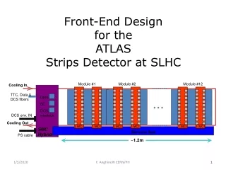
sLHC outer layers • 32 modules/stave • 16 top, 16 bottom • 2x2 FE-I4 modules • Electrical unit = ¼ stave (i.e. 8 modules) • 1 stave cable/el. unit • 1 EOS card/el. unit 38.0 35.9 Module top view Flex down to chip w-bonds stiffener 42.6 Active 33.9 x 40.6 Module side view passives Pixel orientation flex 1.0 mm sensor connector Flex pigtail (connector plugs into page) 15.0 FE FE glue Compressed scale 10.0 L. Gonella - TWEPP 2010 - 21/09/2010
Current (i.e. power) to the modules • Current delivered to the modules via stave cable and module flex • Power unit = electrical unit = 8 modules • Itot = Imod = ~2.4 A • FE-I4 nominal current = ~600 mA • Current to voltage conversion on-chip Shunt-LDO • 2 Shunt-LDO/FE to generate VDDA = 1.5 V and VDDD = 1.2 V • 8 Shunt-LDO on the module operate in parallel FE-I4 FE-I4 1.5V 1.5V 1.2V 1.2V Iin Iout Shunt-LDO Shunt-LDO Shunt-LDO Shunt-LDO Iin Iout Shunt-LDO Shunt-LDO Shunt-LDO Shunt-LDO 1.5V 1.5V 1.2V 1.2V FE-I4 FE-I4 L. Gonella - TWEPP 2010 - 21/09/2010
Shunt-LDO working principle Combination of an LDO and a shunt transistor Shunt-LDO: simplified schematic 2 Shunt-LDOs in parallel: equivalent circuit • Shunt-LDO can be placed in parallel without problems due to mismatch • Shunt-LDO with different Voutcan be placed in parallel • Shunt-LDO can cope with increased Iin • Normal LDO operation when shunt circuitry is off • Shunt regulation circuitry const Iload • LDO regulation loop constant Vout LDO compensates Vout difference L. Gonella - TWEPP 2010 - 21/09/2010
Shunt-LDO characterization Working principle and good performance demonstrated by 2 prototypes Load regulation • Vin and Vout stable until (Iload1 + Iload2) = Isupply(= 0.8 A) • Effective Rout = 60 mΩ (incl. wire bonds and PCB traces) 2 Shunt-LDO in parallel generating different Vout • Vout generation • After saturation • Vout settle @ different potentials • Rin ≈ 2 Ω L. Gonella - TWEPP 2010 - 21/09/2010
Shunt-LDO in a serial powering chain 4 Shunt-LDOs in series generating Vout = 1.5V I source Shunt-LDO 0 Shunt-LDO 2 Shunt-LDO 0 Shunt-LDO 1 Shunt-LDO 2 Shunt-LDO 1 Shunt-LDO 3 Shunt-LDO 3 L. Gonella - TWEPP 2010 - 21/09/2010
Shunt-LDO efficiency • Shunt-LDO sources of inefficiency • LDO dropout voltage Vdrop • Ishunt • ΔV between the 2 Vout needed by the FE • Calculation for ATLAS Pixels L. Gonella - TWEPP 2010 - 21/09/2010
AC-coupling • Needed for module readout in a serial powering scheme • Independently of the powering scheme might be needed for the ATLAS pixels upgrade • @IBL • Concerns about long data transmission lines • Discussion already started about possible need for AC-coupling • @sLHC • Possible compatibility issues between FE-I4 and GBT standards LVDS vs. JESD8-13: SLVS-400 Widely used termination technique in telecommunications • Optimal VCM at RX input • Level shifting • Guard against differences in ground potential 6-7m L. Gonella - TWEPP 2010 - 21/09/2010
Possible AC-coupling implementations • FE-I4 RX input self biased • clk inherently DC-balanced • cmd are not DC balanced but • Slow data (40MHz) • Rail-to-rail receiver, i.e. can accommodate some VCM shift arising from non-DC balanced data Favorite option: direct AC-coupling at RX input Simple, low material Requires self biased RX input & DC-balanced data Downlink: clk & cmd Uplink: data • FE-I4 data are 8b10b encoded • GBT accepts any encoding • RX inputsdo not have integrated self biasing circuitry, but this could eventually be done externally Alternative option: link with feedback Successfully used for the SP proof of principle Higher complexity, more material L. Gonella - TWEPP 2010 - 21/09/2010
Stave protection Proposed protection scheme • 1 Module Protection Chip/module • Could be placed on pigtail • 1 AC-coupled slow ctrl line/MPC from the DCS • 8 lines/stave cables • One capacitor/line on the DCS side DCS MPC module module module MPC • Working principle • DCS can switch on/off selected modules via slow ctrl line • In case of overvoltage • Fast response circuitry in MPC reacts • DCS switches off the module • MPC can be used also for power on sequence MPC stiffener MPC flex connector sensor FE FE L. Gonella - TWEPP 2010 - 21/09/2010
OV Module protection chip • 130nm IBM • Bypass transistor • Independent slow ctrl line & OV protection • OV protection = Silicon controlled rectifier • Preliminary simulations: Iin local VDD Ibp ADC D1 Mbp module DCS C1 C2 D2 GND D3 Vmod ~850mV local GND Slow ctrl Bypass Iout Fast response DGNMOS W = 48mm L = 0.24µm Vgsbp Vmod ~850mV V (V) Ibp Vgsbp AC-signal time (ms) I (A) V (V) C1 = 100nf C2 = Cgs = 33pf D1, D2 = PMOS Imod time (ms) r (Ω) L. Gonella - TWEPP 2010 - 21/09/2010
Prototyping Goal: prototyping an sLHC pixels outer layer with serial powering to try the concept extensively Stave cable • Outer pixel layers prototyping started in the pixel collaboration • 4-chip sensor design in production, FE-I4 submitted • stave cable and type1 cables already prototyped • In progress: stave mechanics and cooling studies, EOS cards design, … • Serial powering related activities in Bonn • Design of LV lines on stave cables • Design of module flex: 1st prototype in production • Allows testing SP, direct powering, direct powering with DC-DC Module flex L. Gonella - TWEPP 2010 - 21/09/2010
x/X0: SP vs. DC-DC – active area Direct powering with DC-DC conv fixedVdrop between V source and converter @sLHC:voltage regulator on PP1, x2 charge pump DC-DC converter in FE-I4 0.2V on stave, 0.8V on Type 1 services x/X0% LV lines (Al only) x/X0% SP (%) • DC-DC conv: Vdrop = 0.2V • Pcable = 5.56% Ptot • LV cables: 0.093% x/X0 • SP @ Pcable = 5.88% Ptot • LV cables = 0.014% x/X0 • ~85% less material x/X0% DC-DC Serial powering LV lines (Al + kapton) : 0.056% x/X0 AC-coupling C: 0.018% x/X0 Protection: 0.010% x/X0 Total: 0.084% x/X0 Direct powering w/ DC-DC conversion LV cable (Al + kapton): 0.139% x/X0 External C: 0.015% x/X0 Total: 0.154% x/X0 L. Gonella - TWEPP 2010 - 21/09/2010
x/X0: SP vs. DC-DC – large η • Services dominate the material budget • Cable channels are saturated DC-DC conv: Vdrop = 0.8V LV cables: 2827.2mm2Al x-section SP @ Vdrop = 0.8V LV cables: 684mm2 Al x-section x/X0 SP ≤ 0.25 x/X0 DC-DC ATLAS inner det. material distribution (incl. IBL) L. Gonella - TWEPP 2010 - 21/09/2010
Conclusions • Scheme architecture definition, power efficiency and material budget calculationsongoing • A custom developed new regulator concept targeting serial powering has been developed: Shunt-LDO • 2 prototypes confirmed working principle and good performance • 2 Shunt-LDOs/FE-I4 • AC-coupling and protection schemes have been proposed • FE-I4 LVDS RX designed with self-biased inputs for direct AC-coupling with DC-balanced data • Simulation of a Module Protection Chip started • Prototyping of an ATLAS pixel detector outer layer featuring serial powering for sLHC has started A serial powering scheme for the ATLAS pixel detector at sLHC is being developed at Bonn University L. Gonella - TWEPP 2010 - 21/09/2010