Download
1 / 43
430 likes | 538 Vues
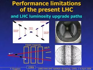
This study by Pavel Belochitskii outlines critical performance limitations and considerations for the ELENA (Extra Low Energy Antiproton) ring. It emphasizes the importance of extraction energy, highlighting that 100 keV enhances captured antiprotons by roughly 30%. Various factors, such as Intra-Beam Scattering (IBS), beam size, and momentum spread, are key to achieving optimal lattice configuration. Requirements for the ring's compact design and specific parameters for electron cooling and beam injection are discussed, focusing on efficient space utilization and maximizing the number of antiprotons per bunch.

E N D
Lattice, Injection Line and General ELENA Performance Limitations Pavel Belochitskii
Choice of extraction energy • Extraction energy Ekin=100 keV allows to increase significantly an amount of captured antiprotons (~30%) • If go to lower energy, one meets strong limitations imposed by: • IBS (Intra Beam Scattering) • transverse space charge limitations (incoherent tune shift) • very high vacuum required • difficult to manufacture foil thinner than 1µm • If go to higher energy: • smaller number of antiprotons due to thicker degrader foil • difficult to equip extraction lines with electrostatic elements (high voltage) Pavel Belochitskii
Preliminary choice of some of the main parameters • Come from experiments: • bunch length must not exceed 300 nsec, or 1.3 m (twice of trap length) • The transverse beam sizes must be around 1 mm (±1σ) -> set requirements to beam emittance at extraction and to beta function values at the focal point (end of transfer line to experiment) • The momentum spread of extracted beam should be small enough to fit requirements of experiments and to avoid problems with beam transport in electrostatic beam lines Pavel Belochitskii
Requirements to lattice which come from layout constraints • Ring must be compact, C= 30.4m (1/6 of AD). This is the minimal length to put required equipment in, and the maximal length to fit properly inside of AD hall • Two extractions from ELENA must be prepared to provide all experiments with beam • The orientations of the injection section and the extraction sections have to help relaxing requirements to the injection and the extraction equipment • Two dedicated straight section have to be prepared, for electron cooling (4.5 m minimum) and for beam injection • The extraction needs less space due to low beam energy of 100 keV and will be done from standard sections • The hexagonal ring compared with the rectangular ring, is much better both from the point of view of making easy injection in and extraction from ELENA ring and using the space available in AD hall in the optimal way • Crane should have access to areas where heavy modules will be installed Pavel Belochitskii
ELENA in AD hall Pavel Belochitskii
Requirements to lattice which come from accelerator physics • betatron tunes must be chosen carefully to provide the maximal space in a tune diagram free from the low order resonances. This will allow operating with the nominal direct space charge tune shift ΔQ = 0.1 or even bigger values, resulting in higher number of antiprotons possible in one bunch • The beta function values in the cooling section should not be too small, otherwise tails in beam distribution will never being cooled • They should not be too big as well, otherwise optics distortion by electron cooler will be essential • The vertical beta function value in bending magnet should be modest (cheaper magnets) • The maximal beta function values should be modest (cheaper equipment for given acceptance) • It is desirable to avoid too small beta function values to limit IBS Pavel Belochitskii
ELENA optics: choice of the bending magnet parameters • Longer magnet makes smaller contribution to the beam focusing in the ring and easy optics adjustment. • Shorter magnet allows operate at very low extraction energy 100 keV with magnetic field not too small • Shorter magnets provide more space for other equipment placement, which is very critical for ELENA ring • Compromised value of bending length 0.97 m and magnetic field at extraction energy 493 G have been chosen • By varying the edge angle at the entrance and exit of bending magnet one can make focusing stronger or weaker in one or another plane • The gap value of 76 mm was chosen to provide fast pumping from magnets and allow installation of bake out equipment Pavel Belochitskii
Choice of the working point • Tunes should allow to operate with maximal incoherent tune shift due to space charge which is critical in ELENA at extraction energy • The working point is chosen near main diagonal Qx - Qy = integer, providing big area in tune diagram free from the most dangerous resonances • The following working point placements have been studied: a) 1.5<Qx,y<2 near Qx - Qy = 1, b) 1<Qx<1.5, 2<Qy<2.5 near Qx - Qy =-1 , and c) 2<Qx<2.5, 1<Qy<1.5 near Qx - Qy =1 • The lattice b) with tunes 1<Qx<1.5, 2<Qy<2.5 has been abandoned soon due to big dispersion function about 4m to 5m which is unacceptable especially in electron cooler Pavel Belochitskii
1.5<Qx,y<2 choice • Qx=1.85, Qy=1.85 is reasonably away from the integer resonances, as well as from the third order resonance 3Qx=5. The working point is chosen near main diagonal Qx - Qy = 0 (only sextupoles driven resonances are shown) • ΔQ≈0.15 can be achieved in case of weak effect of 4th order resonances 4Qx=7, 2Qx + 2Qy = 7 and 4Qy=7 excited by sextupoles (in the second order of perturbation theory) and by octupolar errors in quadrupoles Pavel Belochitskii
2.5<Qx<2, 1.5<Qy<1 choice • Qx=2.3, Qy=1.3 is away from the integer resonances, as well as from the third order resonances 3Qx=7 and Qx - 2Qy = 7. The working point is chosen near main diagonal Qx - Qy = 1 (only sextupoles driven resonances are shown) • ΔQ≈0.2 can be achieved in case of weak effect of 4th order resonances 4Qx=9, 2Qx + 2Qy = 7 and 4Qy=5 excited by sextupoles (in the second order of perturbation theory) and by octupolar errors in quadrupoles Pavel Belochitskii
1.5<Qx<1, 2.5<Qy<2 choice • Qx=1.3, Qy=2.3 is away from the integer resonances, as well as from the third order resonance 3Qx=4. The working point is chosen near main diagonal Qx - Qy = -1 (only sextupoles driven resonances are shown) • ΔQ≈0.2 can be achieved in case of weak effect of 4th order resonances 4Qx=5, 2Qx + 2Qy = 7 and 4Qy=9 excited by sextupoles (in the second order of perturbation theory) and by octupolar errors in quadrupoles Pavel Belochitskii
Possible lattice configurations with periodicity of two (difficulties with beam extraction) Pavel Belochitskii
Possible lattice configurations with periodicity of two (beam extraction is possible) Pavel Belochitskii
Chosen lattice: schematic layout Pavel Belochitskii
Chosen lattice: optics functions Pavel Belochitskii
Chosen lattice: main parameters Pavel Belochitskii
Chromaticity correction • In all lattices it is difficult to find places suitable for placement of focusing sextupole (βx>>βy, decent Dx value) and defocussing (βy>>βx, decent Dx value) sextupoles • Places for sextupoles have to be foreseen during the linear optics design Pavel Belochitskii
Chromaticity correction • In all lattices it is difficult to find places suitable for placement of focusing sextupole (βx>>βy, decent Dx value) and defocussing (βy>>βx, decent Dx value) sextupoles • Places for sextupoles have to be foreseen during the linear optics design Pavel Belochitskii
Electron cooler schematic layout and main parameters Pavel Belochitskii
Effect of electron cooler solenoid on optics • Linear coupling is created by cooler solenoid of length lmsol with magnetic field Bmsol, it is compensated by two compensating solenoids of length lcomp with magnetic field Bcomp= 0.5·Bmsol· lmsol / lcomp placed on each side of cooler • Focusing done by solenioids produces tune shifts • For the nominal field Bmsol =100 G they are δQx=18·10-4 and δQy=19·10-4 . The tune shifts due to compensated solenoids are δQx=32·10-4 and δQy=33·10-4. Totally, for the nominal field in the main solenoid, the tune shifts at extraction energy are δQx=50·10-4 and δQy=52·10-4. • For the field in main solenoid Bmsol =200 G the tune shifts are δQx=0.020 and δQy=0.021 Pavel Belochitskii
Effect of electron beam of cooler on optics • The electron beam of ELENA cooler makes extra defocusing (in both planes) on ring optics. The tune shifts are given by • Effect is more pronounced at extraction energy 100 keV (β=1.46·10-2, γ=1), the classical proton radius r0=1.5410-18 m, the cooling length l0=1.0 m, <βx,y>=β0(1+ l03/(12β0)), beta function values in the centre of the cooler βx,0 =2.1 m, βy,0 =2.2 m and the electron beam current Ie=2 mA tunes shifts are ΔQx,y= -0.012 • Effects of cooler on optics (due to solenoidal fields and due to electron beam) have opposite sign and partly compensate each other • These effect break periodicity of 2, but optics perturbation is weak Pavel Belochitskii
Effect of electron beam of cooler on optics Pavel Belochitskii
Coupling due to errors and its compensation • The tilt errors in quadrupole alignment δφ and the vertical orbit offset in sextupoles δy produce linear coupling in ELENA, which can be estimated in terms of coupling vectors C± as • For δφrms=0.65·10-3 and yrms=2·10-3 m and given beta function values, normalized quadrupole strengths K1=(∂By/ ∂x)/Bρand sextupole strengths K1=(∂2By/ ∂x2)/Bρ, multiplied by their lengths, and assuming no correlation between their strength and phases one finds one finds that C±(r.m.s., quadrupoles)=0.9·10-3, and C±(r.m.s.,sextupoles)=5.1·10-3, resulting in C±(total)=5.1·10-3 Pavel Belochitskii
Coupling due to errors and its compensation • Experience from AD: extra coupling might come from stray fields • Way of compensation: two skew quadrupoles used, properly separated in phase advance (very difficult in ELENA ring) • Fair margins in amplitude foreseen • Only the difference resonance Qx - Qy = 1 will be cared, the WP is well distanced from the sum coupling resonance and it is neglected Pavel Belochitskii
Orbit excursion due to errors • Various sources contribute to orbit excursion: quadrupole misalignments, bending magnet field and tilt errors, cooler solenoid and compensating solenoids tilt errors, stray fields from various sources, earth field • No detailed simulations with ensemble of the rings with randomly distributed errors have been performed yet, instead simple estimations have been done • The r.m.s. deviations have been found: xr.m.s.≈1.3 mm and yr.m.s.≈0.9 mm and the maximal values are expected twice bigger • The systematic measurements of magnetic fields in AD hall in place of ELENA location have been performed, its amplitude doesn’t exceed 0.5 G in any point • Its effect in ELENA was simulated with MADX program. It was assumed that massive conductive equipment like magnets protects beam well from the stray fields. At the non-protected places the value of the magnetic field was assumed 0.5 G everywhere. Pavel Belochitskii
Orbit excursion due to stray fields and earth field in AD hall • The systematic measurements of magnetic field in AD hall in place of ELENA location have been performed, its amplitude doesn’t exceed 0.5 G in any point • Its effect in ELENA was simulated with MADX program. It was assumed that massive conductive equipment like magnets protects beam well from the stray fields. At the non-protected places the value of the magnetic field was assumed 0.5 G everywhere. • For purely vertical filed the maximal horizontal orbit excursion is Xmax=4.2 mm and the r.m.s. excursion Xr.m.s=2.0 mm. After correction with 8 correctors it is reduced down to maximal value Xmax=1.4 mm and r.m.s. excursion Xr.m.s.=0.5 mm. • For the same situation in the vertical plane Ymax=8.4 mm and excursion Yr.m.s.=5.5 mm. After correction the orbit excursion was reduced down to values of Ymax=1.2 mm and Yr.m.s.=0.5 mm Pavel Belochitskii
Orbit correction scheme • The choice of number and positions of combined (DHV) orbit correctors and beam position monitors (BPM) in the ELENA ring is dictated mainly by ring layout. • Two orbit correctors with BPM’s integrated inside are placed at each side of two dedicated straight sections. Other 4 sections have 4 orbit corrector and 6 BPM’s integrated into quadrupoles. Thus totally 10 BPM’s and 8 correctors are foreseen to minimize orbit excursion. • Two horizontal coils are integrated into electron cooler to correct orbit distortion created by toroid kicks. Together with other two correctors on each side of section they will be used for making local horizontal orbit bump around cooler for the best alignment antiproton beam w.r.t. electron beam, hence for fast cooling. • Two small vertical coils will be integrated into cooler as well for making local vertical orbit bump around cooler, together with two vertical correctors placed on each side of cooler section.. • In a similar way two correctors with two integrated BPM’s are placed at the sides of the injection section. Together with using them for an orbit correction they will help to minimize the trajectory and the angle offsets for injected beam, hence reducing its emittance blow up. Pavel Belochitskii
ELENA acceptance and apertures • The ELENA acceptance is defined as big as Ax,y=75 π mm mrad in both planes • The relatively big value was chosen for the reasons: • To avoid beam losses during deceleration from injection energy down to first plateau , where the beam emittance is at its maximal value. The electron cooling is applied for the first time • To keep tails in beam transverse distribution often generated in AD which sometimes include 10% to 20% of total intensity • To take into account emittance blow up appeared after beam transfer from AD to ELENA • With beta function values at electron cooler βx,y≈2 m the beam size for maximal acceptance is σx,y=(75·2)1/2 ≈12 mm which is fits in electron beam radius of 25 mm • The aperture are defined according the formula Pavel Belochitskii
ELENA cycle • Injection of a bunched beam followed by deceleration • Beam cooling at intermediate momentum to counteract beam emittances and momentum spread blow up • Deceleration down to extraction energy, beam cooling, bunching at harmonic h=4, then compression to provide required bunch length and fast extraction • The final goal is delivering to experiments beam 1.3m long with 1σ~1mm Pavel Belochitskii
Nonlinearities in ELENA ring • Nonlinearities from the chromaticity sextupoles: • they are weak. The tunes derivatives w.r.t. beam emittance (εx ,y= 2Ix,y, here I is an amplitude of motion in canonical variables) calculated with MADX + PTC_NORMAl are equal to: ∂Qx/∂εx=-12.2, ∂Qy/∂εy=-3.0,∂ Qx/∂εy=-6.4. • For the particle with the horizontal amplitude corresponding machine acceptance Ax=75 π mm mrad the tune shifts ΔQx=-12.2·75·10-6=-0.9·10-3 and ΔQy=-6.4·75·10-6=-0.48·10-3. For the particle with the vertical amplitude corresponding to a machine acceptance Ay=75 π mm mrad the tune shifts are ΔQx=-0.48·10-3and ΔQy=-3.0·75·10-6=-0.22·10-3. • Nonlinearities from the fringe fields in quadrupoles are small • Nonlinearities from toroids in electron cooler will be studied later, when the corresponding field map will be prepared • The bending magnet field map is prepared, and its analysis has been started. The very strong curvature and noticeable edge angle can contribute to nonlinearities there. Pavel Belochitskii
Intensity limit due to transverse space charge • Experience from AD: extra coupling might come from stray fields • Way of compensation: two skew quadrupoles used, properly separated in phase advance (very difficult in ELENA ring) • Fair margins in amplitude foreseen • Only the difference resonance Qx - Qy = 1 will be cared, the WP is well distanced from the sum coupling resonance and it is neglected Pavel Belochitskii
Intensity limit due to space charge • Most important for bunched beam and a low energies, especially right before extraction • Here rp =1.54·10-18 m, the ring circumference C=30.4m , factors GT=1÷2 and GL=1÷2 depend on transverse and longitudinal beam distributions, • With 60% of deceleration efficiency (3·107 antiprotons injected into ELENA, 1.8·107 antiprotons decelerated down to 100 keV) and basic scenario with 4 bunches extracted the bunch intensity is Nb=0.45·107 Pavel Belochitskii
Intensity limit due to space charge • Example 1, coasting beam at extractionmomentum pc=13.7 MeV/c: • For the beam intensity N=1.8·107 and emittancesεx=εY=4π mm mrad the tune shift is equal to ΔQ=-0.010. For the high intensity extracted beam in AD N=3.6·107 and perfect deceleration efficiency of 100% the tune shift value is still low, ΔQ=-0.020. • Example 2, bunched beam at the end of deceleration (pc=13.7 MeV/c): • For intensity N=1.8·107and for beam which occupies 1/3 of the ring, has emittancesεx,y=15π mm mrad and is more dense at its centre (the coefficients GT and GL are equal to 2) the tune shift is equal to ΔQ= -0.032. For the better deceleration efficiency in ELENA of 80% it goes up to ΔQ= -0.044. • Example 3, bunched beam before extraction (pc=13.7 MeV/c): • For intensity N=1.8·107 distributed in 4 bunches, emittancesεx,y=4π mm mrad and the bunch length lb=1.3 m the tune shift value is ΔQ=-0.121. The coefficients GT and GL are equal to 2. By use of RF system with double harmonics (h=4 and h=8) one can flatten the longitudinal beam distribution making tunes shift smaller in about 25% resulting in ΔQ=-0.096. Pavel Belochitskii
Operation with tune shift ΔQ>0.1is on demand • Operation with experiments number ready for taking a beam smaller than 4 is likely due to • Limited human resources in AD experiments- > difficult to run 24 h / 7days, at least 3 teams required to run continuously • Human limitations: weekends, vacations • Experiment’s time is used not only for taking a beam (collecting data), but for many kind of other work (change/repair equipment, filling in liquid helium, meetings, discussions etc.) • One of the users can be AD / ELENA team for MD’s but this must be schedule properly • High deceleration efficiency in ELENA (more than 60%) may be achieved • Intensity in AD is higher than average (3.5·107 is often the case) Pavel Belochitskii
AD to ELENA transfer line • Using initial part of existing AD extraction line allows to save fair money, time and manpower • The position of ELENA in AD hall is fixed, hence line has to bring AD beam to given point in ELENA • To minimize ELENA septum angle, as well as dispersion mismatch, the separation of AD extraction line and ELENA injection line must be done as fast as possible • To provide fast separation of two lines some elements from AD extraction line will be removed, others moved to new positions and few new installed Pavel Belochitskii
AD beam at extraction: the horizontal emittance in 2011 and 2012 Pavel Belochitskii
AD beam at extraction: the horizontal emittance in 2011 and 2012 Pavel Belochitskii
Separation of AD extraction line and ELENA transfer line • the main difficulty is the lack of space inside of AD tunnel • two short 0.35m and strong 39° bending magnets (ρ=0.5 m, strong vertical focusing) used for separation of lines • two horizontally focusing quadrupoles, one between magnet and the next one right before the shielding • MTV screen to adjust beam position after last magnet Pavel Belochitskii
The second part of ELENA transfer line • After shielding (1.6 thick) another GEM detector is placed • Two quadrupoles in the straight section after shielding, the matching is not straightforward due to fixed positions of 4 of 6 quads • One combined corrector and extra vertical corrector (not shown) upstream to injection kicker for fine tuning position and angle of injected beam • The last element in the line before injection septum is GEM detector • The part of line close to ELENA will be bakeable Pavel Belochitskii
ELENA transfer line optics • Matching of Twiss functions is straightforward, while matching of dispersion and its derivative is impossible (pair of very strong dispersive elements before shielding, weak dispersive elements at the beginning (AD extraction septum) and at the end (ELENA injection septum) line • The attention is paid to minimization of emittance blow up due to mismatch of dispersion and its derivative Pavel Belochitskii
Emittance blow up due to dispersion mismatch • The blow up is characterized by the ratio of emittance after injection and filamentation to the initial emittance H=ε/ε0, where H is • the emittance blow up is minimal for the beam with small momentum spread Δp/p and/or for small values of • To reduce momentum spread of injected beam, electron cooling in AD will be applied during bunch compression. The studies in AD showed that it can be reduced by a factor 3 from Δp/p =4.1·10-4 down to Δp/p =1.3·10-4 (1σ). • With six quadrupoles in injection line available for matching one can find solutions with <1 π mm mrad, hence extra emittance blow up due to dispersion mismatch is defined by value of « 1 π mm mrad which is acceptable Pavel Belochitskii
Emittance blow up due to injection errors • The expected emittance blow up due to misalignments of line quadrupoles is given by the formulae • For typical alignment error of 0.2 mm one finds trajectory offset and angle error at the end of transfer line (kicker position) as big as Δx = 1.6 mm, Δx’= 0.53 mrad, Δy = 3.2 mm, Δx’= 0.77 mrad. • The estimate gives the horizontal emittance blow up Δεx=1.1 π mm mrad and the vertical emittance blow up Δεy=3.4 π mm mrad. Pavel Belochitskii
Thanks for your attention! Pavel Belochitskii