9.9.2 Memory Placement Strategies
210 likes | 671 Vues
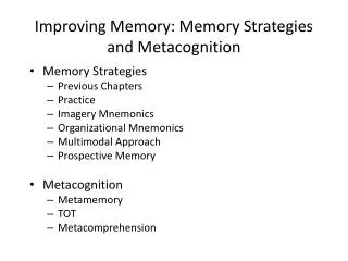
9.9.2 Memory Placement Strategies. Where to put incoming processes First-fit strategy Process placed in first hole of sufficient size found Simple, low execution-time overhead Best-fit strategy Process placed in hole that leaves least unused space around it More execution-time overhead

9.9.2 Memory Placement Strategies
E N D
Presentation Transcript
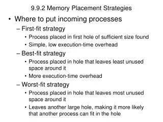
9.9.2 Memory Placement Strategies • Where to put incoming processes • First-fit strategy • Process placed in first hole of sufficient size found • Simple, low execution-time overhead • Best-fit strategy • Process placed in hole that leaves least unused space around it • More execution-time overhead • Worst-fit strategy • Process placed in hole that leaves most unused space around it • Leaves another large hole, making it more likely that another process can fit in the hole
9.10 Multiprogramming with Memory Swapping • Not necessary to keep inactive processes in memory • Swapping • Only put currently running process in main memory • Others temporarily moved to secondary storage • Maximizes available memory • Significant overhead when switching processes • Better yet: keep several processes in memory at once • Less available memory • Much faster response times • Similar to paging
9.10 Multiprogramming with Memory Swapping Figure 9.17 Multiprogramming in a swapping system in which only a single process at a time is in main memory.
Chapter 10 – Virtual Memory Organization Outline10.1 Introduction10.2 Virtual Memory: Basic Concepts 10.3 Block Mapping 10.4 Paging 10.4.1 Paging Address Translation by Direct Mapping 10.4.2 Paging Address Translation by Associative Mapping 10.4.3 Paging Address Translation with Direct/Associative Mapping 10.4.4 Multilevel Page Tables 10.4.5 Inverted Page Tables 10.4.6 Sharing in a Paging System 10.5 Segmentation 10.5.1 Segmentation Address Translation by Direct Mapping 10.5.2 Sharing in a Segmentation System 10.5.3 Protection and Access Control in Segmentation Systems 10.6 Segmentation/Paging Systems 10.6.1 Dynamic Address Translation in a Segmentation/Paging System 10.6.2 Sharing and Protection in a Segmentation/Paging System 10.7 Case Study: IA-32 Intel Architecture Virtual Memory
Objectives • After reading this chapter, you should understand: • the concept of virtual memory. • paged virtual memory systems. • segmented virtual memory systems. • combined segmentation/paging virtual memory systems. • sharing and protection in virtual memory systems. • the hardware that makes virtual memory systems feasible. • the IA-32 Intel architecture virtual memory implementation.
10.1 Introduction • Virtual memory • Solves problem of limited memory space • Creates the illusion that more memory exists than is available in system • Two types of addresses in virtual memory systems • Virtual addresses • Referenced by processes • Physical addresses • Describes locations in main memory • Memory management unit (MMU) • Translates virtual addresses to physical address
10.1 Introduction Figure 10.1 Evolution of memory organizations.
10.2 Virtual Memory: Basic Concepts • Virtual address space, V • Range of virtual addresses that a process may reference • Real address space, R • Range of physical addresses available on a particular computer system • Dynamic address translation (DAT) mechanism • Converts virtual addresses to physical addresses during program execution
10.2 Virtual Memory: Basic Concepts Figure 10.3 Pieces of address spaces exist in memory and in virtual storage. Q: What does OS do in this picture? Q: |V| >> |R|?
10.3 Block Mapping Figure 10.5 Artificial contiguity. Two contiguous instructions In V? In R?
10.3 Block Mapping • Pages • Blocks are fixed size • Technique is called paging • Segments • Blocks maybe of different size • Technique is called segmentation • Block mapping • System represents addresses as ordered pairs Figure 10.6 Virtual address format in a block mapping system.
10.3 Block Mapping Figure 10.7 Virtual address translation with block mapping.
10.4 Paging • Paging uses fixed-size block mapping • Virtual address in paging system is an ordered pair v = (p, d) • p is the number of the page in virtual memory on which the referenced item resides • d is the displacement from the start of page p at which the referenced item is located Figure 10.8 Virtual address format in a pure paging system.
10.4 Paging Figure 10.9Main memory divided into page frames. • Page frame • Fixed-size block of main memory • Begins at a main memory address that is an integral multiple of fixed page size (ps)
10.4 Paging Figure 10.10 Correspondence between virtual memory addresses and physical memory addresses in a pure paging system. Q: What is the significance of dividing the VM and MEM into equal-sized pages?
10.4 Paging • Page table entry (PTE) • Indicates that virtual page p corresponds to page frame p´ • Contains a resident bit to indicate if page is in memory • If so, PTE stores the page’s frame number • Otherwise, PTE stores the location of the page on secondary storage Figure 10.11 Page table entry.
10.4.1 Paging Address Translation by Direct Mapping • Direct mapping • Dynamic address translation under paging is similar to block address translation • Process references virtual address v = (p, d) • DAT adds the process’s page table base address, b, to referenced page number, p • b + p forms the main memory address of the PTE for page p • System concatenates p´ with displacement, d, to form real address, r
10.4.1 Paging Address Translation by Direct Mapping Figure 10.12 Paging address translation by direct mapping.
Group Discussion 9 - 4/2/09 Page table 15 0 0 0 0 Q1. What is the difference between swapping and paging? Q2. Suppose that the secondary storage compartment is not listed in the page table here. What is the physical address? 0 0 0 0 0 0 0 0 0 0 0 0 0 0 0 0 0 0 0 0 0 0 0 0 1 0 0 0 0 0 0 0 6 0 0 0 0 Offset/displacement Page # 5 0 0 1 1 Virtual address 4 0 0 0 0 0 0 0 0 0 1 0 0 0 0 1 0 1 1 0 0 3 1 0 0 0 2 1 1 1 0 1 1 0 0 1 0 1 0 1 0