Download
1 / 8
80 likes | 285 Vues
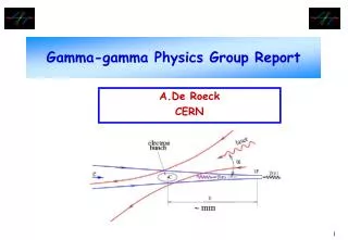
Discussion of gamma-gamma parameters. April 12, 2005 Andrei Seryi. 34. Slide from LCWS05 gamma-gamma summary talk. => estimate ILC-FF9 performance with lower b X and nominal emittances => estimate disruption angles for achievable beams.

E N D
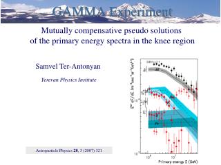
Discussion of gamma-gamma parameters April 12, 2005 Andrei Seryi
34 • Slide from LCWS05 gamma-gamma summary talk
=> estimate ILC-FF9 performance with lower bX and nominal emittances • => estimate disruption angles for achievable beams Left: FF (2001) performance with smaller bX. Picture from gamma-gamma TESLA TDR. Aggressively small emittance was used: 250GeV/beam, gex/y = 2.5/0.03E-6m, by=0.3mm Right: disruption angles of the beams after conversion and beam-beam interactions. Parameters? Possibly, also high lumi aggressively case.
ILC-FF9 with smaller bX (without rematching, change incoming betas) • For nominal emittances, the optimal beta-x is 3mm • Tracked beam sizes are 323*5.21nm (geom. 247.6*4.95nm) • For emittances 10*0.04 the effective betas are 5.1*0.33mm Left: aggressive emittance. Right: nominal emittance. (similar performance as in 2001)
34 • Compare the beam sizes with the values obtained by tracking : • ILC optimistic: tracked = 121nm * 4.37 nm (geometrical is 87.6nm * 4.29nm ) • ILC w/e+e- (at beta 3mm/0.3mm): tracked = 323nm * 5.21nm (geometrical is 247.6nm * 4.95nm) • Correspondingly, the luminosity with tracked beams are: • ILC optimistic: 8.48e+34 instead of 11.8e34 in the table, i.e. 72% • ILC w/e+e- : 2.67e+34 instead of 5.9e34 in the table, i.e. 45%
Disrupted angles for beam with nominal emittances and tracked beam sizes, CAIN simulation. The divergence is much smaller. • Parameters (especially laser) need to be verified Parameters used in CAIN (need to be verified, especially laser parameters): SET ee=250D9, gamma=ee/Emass, an=2.0D10, sigz=0.3*mm, betax=5.1*mm, betay=0.33*mm, emitx=10.0D-6/gamma, emity=4.0D-8/gamma, sigx=Sqrt(emitx*betax), sigy=Sqrt(emity*betay), ntcut=2.5, xangle=0.01, frep=2820*5, off=0.0; SET laserwl=1.05*micron, pulseE=1.57, lambar=laserwl/(2*Pi), omegal=Hbarc/lambar, rlx=0.1*mm, rly=0.1*mm, ! gaussian pulse shape sigt=0.23*mm, powerd=pulseE*Cvel/[Pi*lambar*sigt*Sqrt(2*Pi*rlx*rly)], ! square pulse shape ! tott=0.23*mm, powerd=pulseE*Cvel/[Pi*lambar*ttot*Sqrt(2*Pi*rlx*rly)], xisq=powerd*mu0*Cvel*(lambar/Emass)^2, xi=Sqrt(xisq), eta=omegal*ee/Emass^2, lambda=4*eta, angle=0.0, dcp=5*mm ; ! dcp=CP-to-IP distance
Discussion • The nominal parameters would yield about 2.7E34 luminosity, not including reduction due to conversion coefficient • Disruption angles significantly smaller than +-10mrad, and more like +-5mrad (to be confirmed) • Next: develop QD0-Compensator idea in more details, to have +-10mrad for disrupted beam, thus with factor of two safety, with 20mrad crossing angle • Many other issues to study: e.g. feedback for collision centering, extraction and beam dump, etc. • It is important to continue this discussion with gamma-gamma community to settle on a realistic parameters