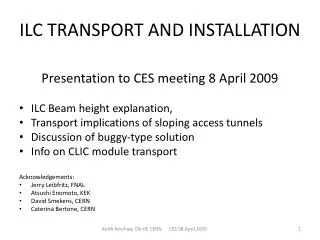
ILC TRANSPORT AND INSTALLATION
ILC TRANSPORT AND INSTALLATION. Presentation to CES meeting 8 April 2009 ILC Beam he ight explanation, Transport implications of sloping access tunnels Discussion of buggy-type solution Info on CLIC module transport Acknowledgements: Jerry Leibfritz, FNAL Atsushi Enomoto , KEK

ILC TRANSPORT AND INSTALLATION
E N D
Presentation Transcript
ILC TRANSPORT AND INSTALLATION Presentation to CES meeting 8 April 2009 • ILC Beam height explanation, • Transport implications of sloping access tunnels • Discussion of buggy-type solution • Info on CLIC module transport Acknowledgements: • Jerry Leibfritz, FNAL • Atsushi Enomoto, KEK • David Smekens, CERN • Caterina Bertone, CERN Keith Kershaw, EN-HE CERN CES 08 April2009
Reason for the (relatively high ) height of the ILC cryomodulesabove the floor (1) (860mm clearance underneath cryomodules) Response from Jerry Leibfritz, FNAL (1) • This is what is used at DESY for FLASH and CMTS, and also at the Fermilab ILCTA. • It is based on the large support girder that sits underneath the first and last cryomodules of a string to counteract the large vacuum load and prevent movement of the cryomodule. The support stand sits on top of this girder. Keith Kershaw, EN-HE CERN CES 08 April 2009
Picture of the first cryomodule on its green support girders at Fermilab. ( cryogenic components not installed ) Keith Kershaw, EN-HE CERN CES 08 April 2009
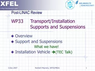
Beam tunnel and service tunnel Keith Kershaw, EN-HE CERN CES 08 April 2009
Reason for the (relatively high) height of the ILC cryomodulesabove the floor (2) Response from Jerry Leibfritz, FNAL (continued) • The cryogenic feedbox and endcaps are designed for this elevation and it would have been too expensive for us at Fermilab to redesign this, so we used basically the same design as DESY. • When we were initially laying out the ILC tunnel, we tried to maximize the use of space, so we set the elevation of the cryomodule to be in the widest part of the diameter of the tunnel, allowing us to move it as close to the wall as possible. • For a machine as big as the ILC, these components could be redesigned, so the cryomodule sits lower, but it would require some engineering effort. TRANSPORT NOTE: THE CURRENT BEAM POSITION IS HIGH ENOUGH TO ALLOW THE USE OF TRANSPORT VEHICLES WHICH INCLUDE THEIR OWN TRANSFER CAPABILITY; IT IS THEREFORE INTERESTING TO LEAVE IT WHERE IT IS Keith Kershaw, EN-HE CERN CES 08 April 2009
LHC Buggies can move at 180 deg to transport direction Keith Kershaw, EN-HE CERN CES 08 April 2009
DESY DwarsloeperDuring Transfer (height 1m) Keith Kershaw, EN-HE CERN CES 08 April 2009
Access ramps to tunnel • CLIC • ILC Asian site Keith Kershaw, EN-HE CERN CES 08 April 2009
CLIC longitudinal section Keith Kershaw, EN-HE CERN CES 08 April 2009
CLIC access ramp tunnel summary Figures based on CLIC Longitudinal section drawing data. Keith Kershaw, EN-HE CERN CES 08 April 2009
Transport implications of access ramps instead of shafts Need to consider special vehicles (e.g. cryo-modules) and standard vehicles (e.g. services). Effect of slope on vehicle design: • Need more traction force (more driven wheels) • Need more braking force (more braked wheels) • Cooling of motors (for long slopes) • Cooling of brakes / motors for braking →Bigger vehicle (integration) Keith Kershaw, EN-HE CERN CES 08 April 2009
Some notes on slope effects Standard electric vehicles • Typically 1.5-2% slope for continuous use at full rated loadwith increased slope the load capacity or the use factor reduces. (see performance chart) Encyclopedie de la Manutention • “rampe ≥ 7% = problèmedélicate” (this is with unbraked trailers) • Effect of 2% slope is to double traction force needed compared with horizontal surface. Keith Kershaw, EN-HE CERN CES 08 April 2009
Example on effect of slope • In the example a tractor with a nominal towing capacity of 20 tonnes can be used on a 10% slope to tow a 6 tonne trailer a maximum of 1600m in one hour. Keith Kershaw, EN-HE CERN CES 08 April 2009
Other transport/slope experience at CERN Buggies for LHC warm magnet installation: • Designed for max slope 8%. • During testing on 7% slope (several passes) overheated after approx 1hour. Special purpose fork lift: • Customized for 14% slope (needed continuous forced ventilation for brakes and motors) • Difficult to find supplier willing to do this. Keith Kershaw, EN-HE CERN CES 08 April 2009
Slope general comments at this stage: • 1.5 - 2% slope means can use standard vehicles (lowest cost most reliable solution) • Up to 7 or 8% slope achievable by reducing standard vehicle capacity to approx one third of nominal (space issues?). • Any steeper slopes will mean that it becomes more difficult to use standard equipment –this will have cost and reliability implications. • In any case equipment for installing cryomodules will be specially designed and built - but what about other equipment? Keith Kershaw, EN-HE CERN CES 08 April 2009
Discussion - Buggies • The 860mm clearance below cryomodules allows the use of a combined transport and transfer vehicle such as the LHC buggies. • The LHC buggies were designed for slope of 8% but did overheat after intensive use on slopes • The transfer using buggies is carried out by rotating the wheels through 90 degrees . The space between ends of LHC warm magnets when being installed is approx 7cm – longitudinal alignment relied on the operators’ skill and care. • The space between the ends of ILC cryomodules is approx 2cm – this would lead to risk of damage using buggy –type solution relying on operator skill for large numbers (1600) modules unless some additional precise alignment is provided. • The LHC buggies were used for transporting warm magnets – less delicate than cryomodules. Keith Kershaw, EN-HE CERN CES 08 April 2009
Buggy concept adaptation for ILC including access ramps • The LHC buggies are 560mm high: for ILC the 860mm clearance underneath cryomodules will allow incorporation of cradles, load suspension, additional cooling and precise positioning tables to allow accurate longitudinal alignment during lateral transfer onto jacks. • Buggy width closer to cryomodule width than outline vehicle shown in ILC cross section (slide 4) Keith Kershaw, EN-HE CERN CES 08 April 2009
Next steps • Next step for CLIC at this stage was small amount of designer work to look into dimensions of vehicle integrated in tunnel and then consider transfer process, as well as vehicle entry into main tunnel . Keith Kershaw, EN-HE CERN CES 08 April 2009
CLIC transport Slides from CLIC workshop in Oct 2008 Keith Kershaw, EN-HE CERN CES 08 April 2009
Transport envelope in cyan – 1125 x 1150 x 2100 Lifting points according to the worst case, i.e. on top of the transport envelope. Intergirder support acceptable assumption for the moment. Keith Kershaw, EN-HE CERN CES 08 April 2009 R. Nousiainen 04092008
Main beam Drive beam 2 CV pipes 250mm Turnaround loop Monorail 3 cable trays 520mm 2 CV pipes 600mm Safe passage Transport train Drive beam Main beam RIGHT VIEW TYPICAL CROSS SECTION CLIC TUNNEL Keith Kershaw, EN-HE CERN CES 08 April 2009
Main beam Drive beam 2 CV pipes 250mm Turnaround loop Monorail 3 cable trays 520mm 2 CV pipes 600mm Safe passage Transport train Drive beam Main beam RIGHT VIEW TYPICAL CROSS SECTION CLIC TUNNEL Keith Kershaw, EN-HE CERN CES 08 April 2009
Main beam Drive beam 2 CV pipes 250mm Turnaround loop Monorail 3 cable trays 520mm 2 CV pipes 600mm Safe passage Transport train Drive beam Main beam RIGHT VIEW TYPICAL CROSS SECTION CLIC TUNNEL Keith Kershaw, EN-HE CERN CES 08 April 2009
Main beam Drive beam 2 CV pipes 250mm Turnaround loop Monorail 3 cable trays 520mm 2 CV pipes 600mm Safe passage Transport train Drive beam Main beam RIGHT VIEW TYPICAL CROSS SECTION CLIC TUNNEL Keith Kershaw, EN-HE CERN CES 08 April 2009
Main beam Drive beam 2 CV pipes 250mm Turnaround loop Monorail 3 cable trays 520mm 2 CV pipes 600mm Safe passage Transport train Drive beam Main beam RIGHT VIEW TYPICAL CROSS SECTION CLIC TUNNEL Keith Kershaw, EN-HE CERN CES 08 April 2009
Jonction chamber with shielding Shaft Loading area Maintenance area 10t Crane Services area Proposal for module lowering and tunnel access Based on Civil Engineering drawings prepared in 2007 Keith Kershaw, EN-HE CERN CES 08 April 2009
Asian site Keith Kershaw, EN-HE CERN CES 08 April 2009