PHASE DIAGRAMS
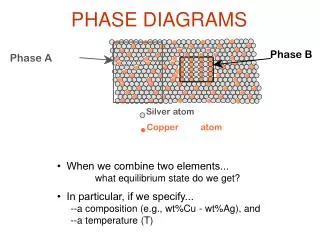
PHASE DIAGRAMS. THEORY AND APPLICATIONS. Some basic concepts. Phase A homogeneous region with distinct structure and physical properties In principle, can be isolated Can be solid, liquid or gas Phase Diagram

PHASE DIAGRAMS
E N D
Presentation Transcript
PHASE DIAGRAMS THEORY AND APPLICATIONS
Some basic concepts • Phase • A homogeneous region with distinct structure and physical properties • In principle, can be isolated • Can be solid, liquid or gas • Phase Diagram • Representation of phases present under a set of conditions (P, T, Composition etc.)
Concepts…... • Phase transformation • Change from one phase to another • E.g. L S, S S etc. • Occurs because energy change is negative/goes from high to low energy state • Phase boundary • Boundary between phases in a phase diagram
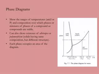
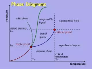
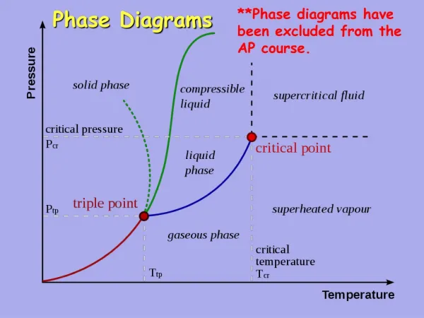
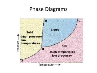
A simple phase diagram System: H2O Liquid Phase boundary Pressure Solid Triple point (Invariant point) Vapor Temperature
Gibb’s Phase Rule P + F = C + 2 P=number of phases C=number of components F=number of degrees of freedom (number of independent variables) F = C - P + 2 Modified Gibbs Phase Rule (for incompressible systems) P + F = C + 1 F = C - P + 1 Pressure is a constant variable
Application of the phase rule At triple point, P=3, C=1, F=0 i.e. this is an invariant point At phase boundary, P=2, C=1, F=1 In each phase, P=1, C=1, F=2
Solidification(cooling) curves Pure metal Alloy L Soldification begins L TL L + S L S Tm TS Solidification complete S S
Construction of a simple phase diagram • Conduct an experiment • Take 10 metal samples(pure Cu, Cu-10%Ni, Cu-20%Ni, Cu-30%Ni………, pure Ni) • Melt each sample and then let it solidify • Record the cooling curves • Note temperatures at which phase transformations occur
L Results T L S L L TL TL L TNi L + S L + S L S Pure Ni TS S TCu S TS S Cu-20%Ni Pure Cu Cu-10%Ni t
Binary isomorphous phase diagram L Temp TNi x x x x x x x x x L+S x x x x x x TCu x x x x x Cu S Ni 0 100 10 20 30 40 50 60 70 80 90 Cu %Ni Ni Composition
Microstructural changes during solidification Pure metal L T L S L S Tm S S t
Microstructural changes during solidification L Alloy T L TL L + S TS S S t
Binary isomorphous phase diagram L T L L T1 T2 L+S T3 L T4 S S CL C0 CS 0 100 10 20 30 40 50 60 70 80 90 A %B B Composition
Notes • This is an equilibrium phase diagram (slow cooling) • The phase boundary which separates the L from the L+S region is called LIQUIDUS • The phase boundary which separates the S from the L+S region is called SOLIDUS • The horizontal (isothermal) line drawn at a specific temperature is called the TIE LINE • The tie line can be meaningfully drawn only in a two-phase region • The average composition of the alloy is CO
Notes….. • The intersection of the tie line with the liquidus gives the composition of the liquid, CL • The intersection of the tie line with the solidus gives the composition of the solid, CS • By simple mass balance, CO = fS CS + fL CL and fS + fL = 1 CO = fS CS + (1- fS) CL Lever Rule
Some calculations • In our diagram at T3, CO= A-40%B, CS=A-90%B and CL=A-11%B • Therefore, fS=29/79 or 37% and fL=50/79 or 63% • If we take an initial amount of alloy =100 g, amt. of solid=37 g (3.7 g of A and 33.4 g of B) and amt. of liquid=63 g (56.07 g of A and 6.93 g of B)
The Eutectic Phase Diagram Liquidus L a + b (TE, CL=CE) Solidus Solvus T L b+L a+L TE b a E a+b CE A Wt%B B
Pure A or B L T L S L CE L b+L a+L TE b L a+b a a+b E Other alloys between A and B a+b CE L A B L+a Wt%B L a+b a+b
Solidification for alloy of eutectic composition T L L b+L a+L TE b a E a+b S a+b CE A B Wt%B a+b
Eutectic microstructure Lamellar structure
L T L b+L a+L b TE a Proeutectica a+b CE a+b A B Wt%B a+b
T L L b+L a+L b L TE a a+b a CE A B Wt%B b particles
The Eutectoid Phase Diagram a + b (TE, Cg=CE) g T g b+ g a+ g TE b a E a+b CE A Wt%B B
Cooling of an alloy of eutectoid composition T g g b+ g g a+ g TE b a E a+b S a+b CE A B Wt%B a+b
Cooling of an alloy of hypoeutectoid composition g T g g b+ g a+ g TE b Pro-eutectiod a a g E a+b Pro-eutectiod a a+b S A B Wt%B a+b
The Peritectic Phase Diagram b (at TP) a + L Note: a and L will react only in a certain proportion= NP:PM L L T b L a+ L TP a N b+ L P M a+b b CP b A Wt%B B
b ( at TP) a + L Note: a and L will react only in a certain proportion= NP:PM NP:PM=1:2 T L L a L a+ L TP a N b+ L a P M L a+b CP b b 25 60 85 10 A Wt%B B
b (at TP) a + L Note: a and L will react only in a certain proportion= NP:PM L L T a L a+ L TP a b N b+ L P M L a+b CP b b A Wt%B B