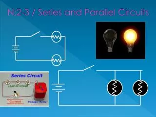
Series – Parallel Dc Circuits
Series – Parallel Dc Circuits. Including Basic Combination Circuits. Jimmie Fouts Houston County Career Academy. Objectives. Review individual series and parallel DC circuit calculations and operation Determine the equivalent circuit resistance for a given combination circuit


Series – Parallel Dc Circuits
E N D
Presentation Transcript
Series – Parallel Dc Circuits Including Basic Combination Circuits Jimmie Fouts Houston County Career Academy
Objectives • Review individual series and parallel DC circuit calculations and operation • Determine the equivalent circuit resistance for a given combination circuit • Determine the voltage drops in a circuit • Determine the current values in a circuit • Apply combination circuit theory to troubleshoot a combination circuit
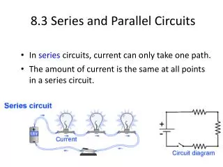
Review : DC Series Circuit Calculation R1 R2 10Ω 30Ω Es = 20 volts Rt = R1 + R2 = 10 Ω + 30 Ω = 40 Ω It = Es / Rt = 20 volts / 40 Ω = 0.5 amps I1 = I2 = It E1 = R1 X I1 = 10 ohm X 0.5 amp = 5 volts E2 = R2 X I2 = 30 ohm X 0.5 amp = 15 volts
Review: DC Parallel Circuit Calculation + Equivalent Resistance = Re = 7.5 Ω R1 R2 10 Ω 30Ω Es = 15 volts
DC Combination Circuits • Often called complex circuits • Not complicated when considered as individual series and parallel circuits • E, I, & R solved using Ohm’s Law!
Basic Procedure for DC Calculations • Reduce the Complex Circuit to a Simple Equivalent • Reduce the circuit to Individual Series and Parallel Circuits • Perform Calculations on the Individual Circuits • Combine Calculations as Appropriate
Combination Circuit Example 10 Reduce to individual series and parallel circuit 20 A 10 ohm resistor is In series with two 20 ohm resistors 20
Determine Simple Series Parallel Parts In the parallel portion of the circuit, the equivalent of two 20 ohm resistors is 10 ohms R1 R2 R3 = Parallel Circuit Equivalent Is 10 Ohms
Combine Calculations as Appropriate • The equivalent circuit is a • 10 ohm resistor in series • with the equivalent circuit • resistor of 10 ohms R1 10 Rt Re 10 Rt = R1 + Re = 10 + 10 Rt = 20 ohms
Use Ohms Law for Circuit values Lets now apply a source voltage of 20 volts. The voltage drop across R1 will be 10 volts. E = 20 volts = 20v X = 10 volts Current through R1 can be calculated. =
Calculations Continued = - = 20 volts – 10 volts = 10 volts
Calculation of Parallel Circuit Values = = 0.5 amps R3 R2 Is calculated in the same manner
The Resulting Circuit values • A summary of the circuit values would therefore be: ohms 1 amp 10 volts ohms ohms = 20 volts 10 volts 0.5 amp 10 volts 0.5 amps = 1 amp = = 20/1 = 20Ω
Troubleshooting Combination Circuits • Look for obvious damaged components • Take voltage readings of individual components (observe safety requirements) • Look for an open or a short circuit condition • Check against expected values
Important safety Note! • Before making any resistance measurements in a circuit, ensure there NO power is being supplied to the circuit! Failure to follow this caution will likely result in equipment damage.
Calculate Expected Values! • It is important to first calculate the expected values before making measurements using the meter! • Using the calculated values, prior to selecting the scale to use, will help prevent meter damage. • Some things to consider: • An open across a resistance in a series circuit will result in a measurement of the source voltage across the defective resistor. • An open across a resistance in a parallel circuit will be difficult to identify, without calculating the expected value. Remember, the voltage across a parallel circuit is the same on all legs of the circuit. An open on a parallel circuit leg will result in the circuit exhibiting a greater resistance and larger voltage drop across the parallel circuit.