Download
1 / 20
200 likes | 221 Vues
This meeting focuses on essential and desirable modifications for the LH2 system post-R&D, including relief circuit upgrades and instrumentation improvements to enhance safety and efficiency.

E N D
MICE Liquid Hydrogen systemPost-R&D design review 15th January 2013 S Watson
Purpose of this meeting • For each R&D outcome • Describe existing situation and why a change has been recommended • Discuss solutions • Categorise into essential (prerequisite for Step IV) and desirable (post-Step IV) • Also to describe interaction of LH2 system with absorber and impact on system safety
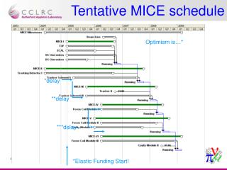
Time constraints • Global MICE schedule delayed – Step IV now 2014 • LH2 system cannot be fully commissioned until LH2 phase of Step IV (2015) • However, decision to carry out preliminary commissioning pre-Step IV (starting around Easter 2013) has been made: • System modifications • AFC interface hardware installation (transfer line etc) • Second R&D programme
Relief circuit Current situation • Much discussed leak from relief lines into vacuum space arising from poorly specified relief valve and seemingly fault burst disk • Currently (and successfully) arrested with a check valve upstream of relief components Reason for modification • Check valve was allowed on the premise that it was only temporary • Check valve in current position stops vacuum poisoning system from operating
Relief circuit Possible action • Move check valve downstream of vac poison connection • Modify/repair current components • Replace current components with vacuum-rated versions • Remove valve entirely and replace burst disk Considerations • Relief valve is very big and expensive • Work required to modify welded pipework is considerable
InstrumentationBed pressure Current situation • Pressure gauge downstream of regulator • Used to control bed temperature Reason for modification • Bed control loop is essentially reactive as it can only respond once pressure drops below regulator setting; a gauge inside the bed would allow a proper feedback loop with pressure setpoint. • Once pressure is above regulator setting, there is no way of knowing what the pressure is i.e. how close to the relief valve pressure it is
InstrumentationBed pressure Possible action • Leave as is • Move existing gauge to other side of regulator • Install new gauge Considerations • There is a broken dial gauge on the bed, upstream of the hand valve • Work required to modify welded pipework is considerable
InstrumentationBed flow in Current situation • Flow meter measures only flow out of bed into transfer line Reason for modification • Only way to measure progress of bed charging process is from the H2 bottle regulator pressure • Inaccurate and requires presence in MICE Hall • No way to measure flow during empty sequence • No direct indication of boil-off rate, although it is clear from the temperature and pressure readings when the sequence has finished or the absorption rate is slower than the boil-off
InstrumentationBed flow in Possible action • Leave as is • Place flow meter in current pressure gauge (PG7) port • Install new flow meter • In H2 charge line • In gas panel pipework • Replace current flow meter with bi-directional version Considerations • Work required to modify welded pipework is considerable • Flow meter in charge line would only be useful during charge sequence, not empty sequence • Vice versa for replaced flow meter
Nitrogen flow Current situation • Two bottle packs with a change-over regulator situated on platform outside the Hall. Reason for modification • At a flow rate of 5l/min, each bottle pack lasts less than 2 weeks, meaning pack changing is required for run periods longer than a month. • Pack changing is awkward with current platform layout.
Nitrogen flow Possible action • Leave as is • Install a LN2 Dewar to supply gas Considerations • Discussions regarding a Dewar are already progressing
Viewing ports Current situation • Gas panel is completely opaque apart from one small viewing panel on the front Reason for modification • Critical hand valves are difficult to see from port • Other dial gauges (non-critical) not visible • Ice build-up on hydride bed not visible
Viewing ports Possible action • Leave as is • Modify panels for increased visibility Considerations • None
Control system • User interface (general improvements) • Unit consistency • Error messages and abort procedures • Development of EPICS monitoring, particularly alarm handler • Gas detection system improvements • Control room improvements