Hydrogen system R&D
Hydrogen system R&D. R&D programme – general points. Hydrogen absorber system incorporates 2 novel aspects Hydrogen storage using a hydride bed Hydrogen absorber with cooling from a cryocooler


Hydrogen system R&D
E N D
Presentation Transcript
R&D programme – general points • Hydrogen absorber system incorporates 2 novel aspects • Hydrogen storage using a hydride bed • Hydrogen absorber with cooling from a cryocooler • R&D programme is an important element to reduce both technical and financial risk and to develop the safety case • Aim is to develop an integrated programme for the absorber and hydrogen system involving international groups within the MICE collaboration – two strings • Hydrogen system R&D - to be done at RAL – located in the MICE Hall – essential to development of expertise and safety approval • Absorber R&D – to be done within the Collaboration • Aim for the two elements finally to be brought together at RAL
R&D system layout • Can replace the overall system slide which follows by the slide of the R&D system if you think it is better for this presentation
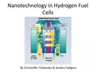
H Detector 2 H Detector 2 Hydrogen System Baseline layout High level vent High level vent High level vent High level vent Vent Vent outside outside Non return Non return flame flame valve valve Vent manifold Vent manifold Vent manifold Vent manifold arrester arrester 0.1 bar 0.1 bar H H Detector Detector Hydrogen zone 2 Hydrogen zone 2 2 2 Extract hood Extract hood VP2 VP2 PV8 PV8 P1 P1 P P Metal Hydride Metal Hydride P P PV7 PV7 storage unit storage unit P P (20m (20m capacity) capacity) 3 3 PV2 PV2 PV1 PV1 Chiller Chiller /He /He 1 bar 1 bar ater Unit ater Unit Tbed Tbed Buffer Buffer Hydrogen Hydrogen PV3 PV3 1 m 1 m 3 3 vessel vessel supply supply PV4 PV4 P P Fill valve Fill valve P P HV1 HV1 Coolant Coolant Out In Out In P2 P2 P P 0.5 bar 0.5 bar 0.9 bar 0.9 bar P3 P3 HV2 HV2 P P P P Purge valve Purge valve P P P P P P H H Detector Detector 2 2 Safety window Purge valve Purge valve HV3 HV3 Absorber window 0.9 bar 0.9 bar PV6 PV6 Nitrogen Nitrogen Helium Helium supply supply supply supply 0.5 bar 0.5 bar VP1 VP1 - - Pressure Pressure Non-return valve Pressure gauge Pressure regulator Pressure Bursting disk Bursting disk Valve Valve P P P P VP VP Vacuum pump Vacuum pump relief valve relief valve
Hydrogen System Development – Scope (1) • To construct a prototype hydrogen handling system at RAL which will become the first full system of MICE • This will consist of 2 main parts • The external system – which will be in the final form • to deliver H2 to the absorber and store the H2 in the hydride beds • The safety system to vent H2 in failure modes- to include relief valves and buffer volume • The dummy absorber • The absorber will be simulated by a simple cryostat with a containment vessel to contain 20litres H2 – operated from a condensing pot with a cryocooler
Hydrogen System Development – Scope (2) • The development programme will address the following issues: • Confirm the working parameters of a hydride bed in the regimes of storage, absorption and desorption of hydrogen ? • Purity of hydrogen and effects of impurities. • Hydride bed heating/ cooling power requirements. • Instrumentation and control required for the operation of the system • Safety aspects including - safety relief valves, sensors and interlocks and safety documentation • The R&D programme will enable the final design for the MICE hydrogen system to be confirmed and the HAZOP to be completed.
Hydrogen System R&D WP(1) • Initial Design • H2 handling system • Confirmation of • components on H2 circuit diagram • pipe sizes, mass flows, pressure drops, relief valve specifications, venting, manifolding • Vacuum and purging systems • layouts in hall • H2 zones • Basic specifications for purchased items
Hydrogen System R&D WP(1) • Initial Design • Dummy absorber • Cryostat design • H2 containment vessel, condensing pot, internal pipework components • Pre - cooling – heat exchanger etc • Heater for load simulation and H2 boil off • Instrumentation • Data acquisition • Outline definition of test programme and proposals for fault condition simulation
Hydrogen System R&D WP(1) • Conclusion of WP(1) • Update cost estimates for main components • Internal Engineering and Safety Review • Aim will be confirm the scope of the R&D programme and release the stage of WP2 – detailed design and procurement
Hydrogen System R&D WP(2) • Detailed design- Procurement – Installation • Detailed design of manufactured components – cryostat + dummy absorber, buffer volume • Specification of commercial items – hydride beds, relief valves, vacuum systems • Definition of installation procedure and specification of infrastructure such as manifolds for installation • Procurement of components • Preparation of operation and test procedures • Preparation of safety case
Hydrogen System R&D WP(2) • Conclusion of WP(2) • Update of Engineering and Safety Review • Aim to include additional aspects based on • More detailed procedures for operation and test • HAZOP
Hydrogen System R&D WP(3) • Installation and commissioning • Installation of system components • Subsystem test and commissioning • Proof of gas handling with He • Leak testing • Check instrumentation and overpressure valve operation • Check precooling and cryocooler operation • Review and permission to operate with H2
Hydrogen System R&D WP(4) • Test Programme • Purging sequence • H2 transfer into hydride bed • Local operation of hydride bed • Initial transfer of H2 into dummy absorber • Dummy absorber cooldown, fill and warmup • H2 filling /emptying • H2 return to hydride bed • System control • Fault scenarios • Vacuum failure test of venting
Hydrogen System R&D Schedule • Outline Schedule • WP1 Initial design Jan – May 05 • WP2 Detailed design and procurement June – Dec 05 • WP3 Installation and commissioning Jan – April 06 • WP4 Test Programme June – Oct 06
Absorber R&D - scope • Scope • Modelling and operation of a dummy absorber from a cryocooler system • Simulation of final system thermal and operational conditions • Proof of principle for absorber supports and shielding • Specific demonstration of operation at helium temperatures with liquid helium using a cryocooler – establish margins • The aim will be to undertake this programme using the resources of the International Collaboration – the specific UK role in this is still to be defined – funds identified to ensure the programme is viable
Absorber R&D R&D module concept MICE Absorber