Ch 5. Wireless Network Principles
Ch 5. Wireless Network Principles. Myungchul Kim mckim@icu.ac.kr. SESSION: Wireless Communication Principles. Wireless Network Classification Transmitters/Receivers Antennas Frequency Allocation Propagation Modes Noise Characteristics Signal Encoding Error Detection and Correction.

Ch 5. Wireless Network Principles
E N D
Presentation Transcript
Ch 5. Wireless Network Principles Myungchul Kim mckim@icu.ac.kr
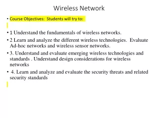
SESSION: Wireless Communication Principles • Wireless Network Classification • Transmitters/Receivers • Antennas • Frequency Allocation • Propagation Modes • Noise Characteristics • Signal Encoding • Error Detection and Correction
Wireless Frequency Allocation • Radio frequencies range from 9KHz to 400GHZ (ITU) • Microwave frequency range • 1 GHz to 40 GHz • Directional beams possible • Suitable for point-to-point transmission • Used for satellite communications • Radio frequency range • 30 MHz to 1 GHz • Suitable for omnidirectional applications • Infrared frequency range • Roughly, 3x10¹¹ to 2x10¹⁴ Hz • Useful in local point-to-point multipoint applications within confined areas
Wavelength Wireless Radio Spectrum; Frequency Allocation Frequency Gamma-rays X-rays 3000 GHz Infrared 0.1 m 300 GHz 1 mm THF - terribly high frequency 30GHz 10 mm EHF - extra high frequency Micro Waves 3GHz 100 mm SHF - super high frequency 300 MHz 1m UHF - ultra high frequency 30 MHz 10 m VHF - very high frequency Radio Waves 3MHz 100 m HF - high frequency 300KHz 1 Km MF - medium frequency 30Khz 10 Km LF - low frequency 3KHz 100 Km VLF - very low frequency Source: Bekkers, R. and Smits, J., “Mobile Telecommunications”, Artech, 2000.
Frequency Regulations • Frequencies from 9KHz to 300 MHZ in high demand (especially VHF: 30-300MHZ) • In wireless, lower frequencies (omnidirectional) • Two unlicensed bands in the US (counterparts elsewhere) • Industrial, Science, and Medicine (ISM): 2.4 GHz • Unlicensed National Information Infrastructure (UNII): 5.2 GHz • Regional, national, and international issues • Procedures for military, emergency, air traffic control, etc • Different agencies license and regulate • www.fcc.gov - US • www.open.gov.uk/radiocom -- for UK • Others (e.g., ETSI, five agencies in Japan) • Interferences across national borders handled through Radio Communications Bureaus
ITU (International Telecom Union) • Headquartered in Geneva (next to UN) • Several sectors: • ITU-R(radiocommunications)- several study groups and World Radio Conferences (WCRs) • ITU-T (standards) - subsummed formerly CCITT • ITU-D (development) - developing countries
National Telecommunications and Information Administration (NTIA - www.ntia.gov) • NTIA is part of The United States Commerce Department • Maintain a spectrum chart, dated March 1996, that depicts the radio frequency spectrum allocations to radio services operated within the United States. • Graphically partitions the radio frequency spectrum, extending from 9 kHz to 300 GHz, into over 450 frequency bands • Copies of this chart can be viewed on line athttp://www.ntia.doc.gov/osmhome/allochrt.html; and printed copies of this chart are available from the U.S. Government Printing Office (ph: 202 512 1800; stock #: 003-000-00652-2 cost is: $6.00
Location Based Services (LBSs) • Techniques: • Cell-id based • GPS assisted • Angle of arrival • Others
Wireless Transmission Antenna Antenna • Wireless Communication systems consist of: • transmitters • Antennas: radiates electromagnetic energy into air • Receivers • In some cases, transmitters and receivers are on same device, called transceivers (e.g., cellular phones) Transmitter Receiver
Transmitters Antenna Amplifier Mixer Filter Amplifier Transmitter Oscilator • Suppose you want to generate a signal that is sent at 900 MHz and • the original source generates a signal at 300 MHZ. • Amplifier - strengthens the initial signal • Oscilator - creates a carrier wave of 600 MHz • Mixer - combines original signal with oscilator and produces 900 MHz • (does modulation, etc) • Filter - selects correct frequency (required by FCC) • Amplifier - Strengthens the signal before sending it (higher f in some cases) • Receivers perform similar operations but in reverse direction
Antennas • An antenna is an electrical conductor or system of conductors to send/receive RF signals • Transmission - radiates electromagnetic energy into space • Reception - collects electromagnetic energy from space • In two-way communication, the same antenna can be used for transmission and reception Directional Antenna (higher frequency) Omnidirectional Antenna (lower frequency)
Radiation Patterns • Radiation pattern • Graphical representation of radiation properties of an antenna • Depicted as two-dimensional cross section • Reception pattern • Receiving antenna’s equivalent to radiation pattern Antenna Types • Isotropic antenna (idealized) • Radiates power equally in all directions • Dipole antennas • Half-wave dipole antenna (or Hertz antenna) • Quarter-wave vertical antenna (or Marconi antenna) • Parabolic Reflective Antenna (highly focussed, directional)
Smart Antennas • Basic idea: propagate signals to follow objects as they move around and minimize noise. • Mixture of: • Switched beam systems: a number of fixed beams at an antenna site – the beam with least interference and best signal strength is chosen. • Adaptive antennas: array of antennas that can adjust patterns based on noise, interference, and location of objects • Great deal of activity • Liberti, J. and Rappaport, T., “Smart Antennas for Wireless Communications”, Prentice Hall
Terrestrial Microwave (1GHz to 40GHz) • Description of common microwave antenna • Most common: Parabolic "dish", 3 m in diameter • Fixed rigidly and focuses a narrow beam • Achieves line-of-sight transmission to receiving antenna (relays used in between) • Located at substantial heights above ground level • Applications • Long haul telecommunications service (instead of fiber, coax) -- requires less repeaters but line of sight • Short point-to-point links between buildings (e.g, closed circuit TV, LANs, bypass local telephone companies) • Most common BW= 4GHZ (can give up to 200 Mbps) • Loss proportional to log (d/w)
Satellite Microwave (1GHz to 20 GHz, typically) • Description of communication satellite • Microwave relay station • Used to link two or more ground-based microwave transmitter/receivers • Receives transmissions on one frequency band (uplink), amplifies or repeats the signal, and transmits it on another frequency (downlink) • Applications • Television distribution (e.g., PBS uses satellite exclusively) • Long-distance telephone transmission between telephone exchange offices • Private business networks (lease channels, expensive)
Broadcast Radio (30 MHz to 1GHz) • Description of broadcast radio antennas • Omnidirectional (main differentiator from microwave) • Antennas not required to be dish-shaped • Antennas need not be rigidly mounted to a precise alignment • Applications • Broadcast radio • VHF and part of the UHF band; 30 MHZ to 1GHz • Covers FM radio and UHF and VHF television • Due to new apps, the frequency range is expanded frequently • Infrared • does not penetrate walls • used in remote control devices
LOS Wireless Transmission Impairments • Attenuation and attenuation distortion • Free space loss • Noise • Atmospheric absorption • Multipath • Refraction • Thermal noise
Attenuation • Strength of signal falls off with distance over transmission medium • Attenuation factors for unguided media: • Received signal must have sufficient strength so that circuitry in the receiver can interpret the signal • Signal must maintain a level sufficiently higher than noise to be received without error • Attenuation is greater at higher frequencies, causing distortion • Approach: amplifiers that strengthen higher frequencies
Categories of Noise • Thermal Noise • Intermodulation noise • Crosstalk • Impulse Noise
Digital versus analog communications Fig 5-13
Signal Encoding (Modulation) • Modulation of digital signals • When only analog transmission facilities are available, digital to analog conversion required • Modulation of analog signals • A higher frequency may be needed for effective transmission • Modulation permits frequency division multiplexing • PCM and variants used frequently
Pulse Code Modulation • Based on the sampling theorem (sample rate should be higher than twice highest frequency) • Each analog sample is assigned a binary code • Analog samples are referred to as pulse amplitude modulation (PAM) samples • The digital signal consists of block of n bits, where each n-bit number is the amplitude of a PCM pulse • 8000 samples per second, 8 bits for levels (256)
Pulse Code Modulation Amplitude Samples This shows 12 samples, each sample represents the amplitude of the wave. These samples as sent as digital data and then reconstructed into the original signal on the receiving side.
Delta Modulation • Analog input is approximated by staircase function • Moves up or down by one quantization level () at each sampling interval • The bit stream approximates derivative of analog signal (rather than amplitude) • 1 is generated if function goes up • 0 otherwise
Delta Modulation Analog Signal Signal Amplitude Staircase Function Time
Multiple Access Techniques Session4 Session2 Session3 Session3 Session4 Session1 Frequency Session2 Frequency Session1 Time Time Time Division Multiple Access (TDMA) PCM, PSK (6 ms frames) Used by AT&T wireless, Bellsouth, Ericsson Frequency Division Multiple Access (FDMA) All sessions based on a code Rarely used at present Frequency Time Spread spectrum, Direct Used by Sprint PCS, 3G systems Code Division Multiple Access (CDMA)
FDMA and TDMA • FDMA: • FM radio divides the spectrum into 30 Khz channels. • FDMA divides 30 Khz channels into 3 (10 KHz each) • Base station cost is high and very limited capacity • TDMA: • available since 1992 • each subscriber transmits at different times • 6 millisecond frames, each divided into 1 ms time slots • each time slot has a header and data • errors may corrupt headers and cause time slots and in some cases the whole frame is lost • TIA standard IS-54 defines the TDMA interface between a mobile station and cell-site radio (uses PCM for speech encoding, DQPSK for modulation) • Call quality is similar to FDMA but can handle more calls (AT&T) • Several extensions of TDMA (can support 15 users per voice channel)
CDMA • Based on spread spectrum - direct sequencing is more prevalent (TIA IS-95) • Groups of bits from digitized speech are tagged with a unique code that is associated with a cellular call. • Several cellular calls are combined and transmitted over 1.25MHz and then reassembled on the receiver side • Receiver detects a signal by tuning to correct phase position between incoming and locally generated signals from code • Speech coder operates at a variable rate (fully when user is talking) • Adjusts for near-far power adjustments (nearer stations generate less powerful signals) • When powered on, the mobile system knows the CDMA frequency, so it tunes to that frequency and searches for a pilot signal (pilot signals represent base stations) • Mobile station will pick the strongest pilot and register • When moving from cell to cell, new pilot is picked up
TDMA versus CDMA Controversy • TDMA and CDMA are accepted TIA (telecom Industry Association) standards (IS-54, IS-95) • Hardware vendors are lobbying hard • Many, many variants in industry • Performance reports are conflicting and confusing in terms of: • Call clarity: CDMA appears to be better but questioned • Network capacity: CDMA may be more efficient than TDMA • Privacy: CDMA codes provide more privacy • Economy: TDMA allows same equipment for multiple users • Maturity: TDMA is very mature (in use since 1992) • More features; TDMA offers more but CDMA can do it also
Spread Spectrum • Input is fed into a channel encoder • Produces analog signal with narrow bandwidth • Signal is further modulated using sequence of digits • Spreading code or spreading sequence • Generated by pseudonoise, or pseudo-random number generator • Effect of modulation is to increase bandwidth of signal to be transmitted • On receiving end, digit sequence is used to demodulate the spread spectrum signal • Signal is fed into a channel decoder to recover data
Frequency Hopping Spread Spectrum (FHSS) • Signal is broadcast over seemingly random series of radio frequencies • Signal hops from frequency to frequency at fixed intervals • Channel sequence dictated by spreading code • Receiver, hopping between frequencies in synchronization with transmitter, picks up message • Advantages • Eavesdroppers hear only unintelligible blips • Attempts to jam signal on one frequency succeed only at knocking out a few bits
Frequency Hopping Spread Spectrum (FHSS) Energy Data Bits 4 7 5 1 6 8 3 2 Frequency f1 f2 f3 f4 f5 f6 f7 f8
Direct Sequence Spread Spectrum (DSSS) • Each bit in original signal is represented by multiple bits in the transmitted signal • Spreading code spreads signal across a wider frequency band • Spread is in direct proportion to number of bits used • One technique combines digital information stream with the spreading code bit stream using exclusive-OR
Code-Division Multiple Access (CDMA) • Basic Principles of CDMA • D = rate of data signal • Break each bit into kchips • Chips are a user-specific fixed pattern • Chip data rate of new channel = kD
CDMA Example • If k=6 and code is a sequence of 1s and -1s • For a ‘1’ bit, A sends code as chip pattern • <c1, c2, c3, c4, c5, c6> • For a ‘0’ bit, A sends complement of code • <-c1, -c2, -c3, -c4, -c5, -c6> • Receiver knows sender’s code and performs electronic decode function • <d1, d2, d3, d4, d5, d6> = received chip pattern • <c1, c2, c3, c4, c5, c6> = sender’s code
CDMA Example • User A code = <1, –1, –1, 1, –1, 1> • To send a 1 bit = <1, –1, –1, 1, –1, 1> • To send a 0 bit = <–1, 1, 1, –1, 1, –1> • User B code = <1, 1, –1, – 1, 1, 1> • To send a 1 bit = <1, 1, –1, –1, 1, 1> • Receiver receiving with A’s code • (A’s code) x (received chip pattern) • User A ‘1’ bit: 6 -> 1 • User A ‘0’ bit: -6 -> 0 • User B ‘1’ bit: 0 -> unwanted signal ignored
Coping with Data Transmission Errors • Error detection codes • Detects the presence of an error • Automatic repeat request (ARQ) protocols • Block of data with error is discarded • Transmitter retransmits that block of data • Error correction codes, or forward correction codes (FEC) • Designed to detect and correct errors
Error Detection Process • Transmitter • For a given frame, an error-detecting code (check bits) is calculated from data bits • Check bits are appended to data bits • Receiver • Separates incoming frame into data bits and check bits • Calculates check bits from received data bits • Compares calculated check bits against received check bits • Detected error occurs if mismatch
Wireless Transmission Errors • Error detection requires retransmission • Detection inadequate for wireless applications • Error rate on wireless link can be high, results in a large number of retransmissions • Long propagation delay compared to transmission time • Best to correct errors by using • Block Error Correction • Turbo Codes
Block Code (Error Correction) • Hamming distance – for 2 n-bit binary sequences, the number of different bits • E.g., v1=011011; v2=110001; d(v1, v2)=3 • For each data block, create a codeword • Send the codeword • If the code is invalid, look for data with shortest hamming distance (possibly correct code) Datablock (k=2) Codeword (n=5) 00 00000 01 00111 10 11001 11 11110 Suppose you receive codeword 00100 (error) Closest is 00000 (only one bit different)
Turbo Codes • Good block error correction requires large codewords • Large codewords are complex to process and waste bandwidth • Turbo codes break the codewords into two • Two encoders on transmitters • Two decoders on receivers • Shown to be very efficient • Main limitation: decoding is complex and introduces delays • Many applications in deep space communications • Very active area of work