Download
1 / 80
800 likes | 976 Vues
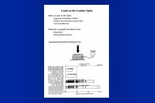
In Vivo Loads on the Lumbar Spine. Standing and walking activities: 1000 N Supine posture: ~250 N Standing at ease: ~500 N Lifting activities: >> 1000 N Lifting 10 Kg, back straight, knee bent: 1700 N Holding 5 Kg, arms extended: 1900 N

E N D
In Vivo Loads on the Lumbar Spine • Standing and walking activities: 1000 N • Supine posture: ~250 N • Standing at ease: ~500 N • Lifting activities: >> 1000 N • Lifting 10 Kg, back straight, knee bent: 1700 N • Holding 5 Kg, arms extended: 1900 N (Nachemson 1987; Schultz 1987; McGill 1990; etc.)
In Vivo Loads on the Cervical Spine EXERCISE LATERAL A - P SHEAR COMPRESSION (N) SHEAR (N) (N) 2 122 Relaxed 0 778 Left Twist 33 70 1164 Extension 0 135 558 Flexion 0 31 758 Left 125 93 Bending Moroney, et al., 6:713 - 720, 1988 J. Orthop. Res. Choi and Vanderby, ORS Abstract, 1997
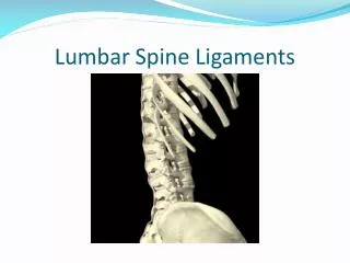
Physiologic Spinal Motion 3-D Motion: - Flexion/Extension (Fig) - Right/Left Lateral Bending - Right/Left Axial Rotation In normal condition, the spine should be flexible enough to allow these motions without pain and trunk collapse (Flexibility).
Biomechanical Functions of the Spine • Protect the spinal cord • Support the musculoskeletal torso • Provide motion for daily activities
Requirements for Normal Functions Stability + Flexibility Stability
Ex vivo Studies of the Lumbar Spine • Range of Motion of the Lumbar Motion Segments: • Flexion/extension: 12 - 17 degrees • Lateral bending: 6 - 16 degrees • Axial rotation: 2 - 4 degrees (White and Panjabi 1990) • Lumbar motion segments can withstand 3000 N - 5000 N in compression without damage. (Adams, Hutton, et al. 1982)
P Ex Vivo Studies of the Lumbar Spine • Without active muscles, • When constrained to move in the frontal plane, lumbar spine specimens buckle at P < 100 N. • (Crisco and Panjabi, 1992) • In the sagittal plane, a vertical compressive load induces bending moment and results in large curvature changes at relatively smaller loads. When exceeding the ROM, further loading can cause damage to the soft tissue or bony structure. • (Crisco et al., 1992)
Neuromuscular Control System Spinal Muscles Spinal Column How to obtain spinal stability and flexibility?
HYPOTHESIS • The resultant force in the spine must be tangent to the curve of the spine (it follows the curvature). • This resultant force (follower load) imposes no bending moments or shear forces to the spine. • As a result, the spine can support large compressive loads without losing range of motion. Curvature of the Lumbar Spine L1 Follower Load L2 L3 L4 Center of Rotation L5 Compressive Follower Load
Loading Cable Cable Guide Compressive Follower Load Cervical FSU Strength > 2000 N (450 pounds)
No Follower Load With Follower Load 10 10 8 8 6 6 4 4 2 2 0 0 -2 -2 -4 -4 -6 -6 -8 -8 -10 -10 10 10 8 8 6 6 4 4 2 2 0 0 -2 -2 -4 -4 -6 -6 -8 -8 -10 -10 Flexion / Extension Motions L2-3 L3-4 Rotation Angle (deg) Rotation Angle (deg) -8 -6 -4 -2 0 2 4 6 8 -8 -6 -4 -2 0 2 4 6 8 : p < 0.1 : p <0.05 Applied Moment (Nm) Applied Moment (Nm) L4-5 L5-S1 Rotation Angle (deg) Rotation Angle (deg) -8 -6 -4 -2 0 2 4 6 8 -8 -6 -4 -2 0 2 4 6 8 Applied Moment (Nm) Applied Moment (Nm)
Effect of Follower Load Experimental results showed: • Significantly increased stability • No significant limitation of flexibility (or segmental motion range)
Muscle Force Line of Action Lumbar Spine Model x x L1 L2 L3 l5 L4 l4 l3 L5 l2 l1 y y Frontal Plane Sagittal Plane
Nomenclature x yo: initial curvature of the spine yn: horizontal elastic deformation for the nth segment an: initial horizontal distance from the origin at the nth node n: horizontal elastic deformation at the nth node EIn: bending stiffness at the nth level Fn: muscle force on the the nth level n: angle defining the line of action of the nth muscle Pon: external vertical force on the nth level Pn: Pon + Fnsin n (total vertical force) Hn: external horizontal force on the nth level Mn: external moment acting on the nth level M3 H3 F3 P3 3 y
Governing Equations for Follower Load From the classic beam-column theory; For Region n: ln+1 x ln, n = 1, …, 5 (Note: l6 = 0) where i = 1,…, 5
Governing Equations for Follower Load Boundary Conditions: fixed at the sacrum, y5(0) = 0 and y5(0) = 0 Displacement and Slope Continuity Equations: yi(li+1) = yi+1(li+1) i = 1,…,4 yi(li+1) = yi+1(li+1) i = 1,…,4
Solution Procedures 20 unknowns for the elastic deformations, y1, y2, y3, y4, and y5: - 10 constants arising from 5 homogeneous solutions to 2nd-order DE - 5 unknown elastic deformation values at 5 vertebral centroids (i) - 5 muscle forces (Fi) 15 Equations: - 5 differential equations - 2 boundary conditions - 8 displacement and slope continuity equations 5 more equations: - constraints on the muscle forces to produce follower load
Constraints for Follower Load Ri = Resultant force at ith level Ri need to be tangent to the curve to be a follower load. at L2 at L1 L1 H1 H2 H1 F1 L2 R1 Po1 Po2 Po1 R2 L3 R2 R1 R3 L4 F1 R1 R4 L5 R5 F2 n = 1,…, 5 (Note: a6 = 0, 6= 0, l6 = 0)
Model Response to Follower Load up to 1200 Nin Frontal Plane
Model Response to Follower Load up to 1200 N In Frontal Plane Po1 = 1040 N L1 R1=1159 N L2 F1 = 163 N F2= 35.5 N R2=1177 N L3 = F3 = 27.2 N R3=1188 N L4 R4=1197 N F4 = 25.2 N L5 F5 = 29.5 N R5=1201 N 0.2 m
Model Responses In Frontal Plane Po1 = 350 N Po2 = Po3 = Po4 = Po5 = 50 N Po1 L1 R1=388 N L2 F1 = 51.9 N F2= 6.80 N R2=441 N L3 = F3 = 6.74 N R3=494 N L4 R4=546 N F4 = 8.23 N L5 F5 = 12.3 N R5=598 N 0.2 m
Model Responses In Frontal Plane Po1 = Po2 = Po3 = Po4 = Po5 = 110 N Po1 L1 R1=122 N L2 F2= 6.74 N R2=236 N L3 = F1 = 16.1 N R3=346 N F3 = 6.74 N L4 R4=457 N F4 = 3.04 N L5 F5 = 9.45 N R5=569 N 0.2 m Model responses vary with changes in external load distribution and muscle origin distance as well.
Tilt of L1 in the Sagittal Plane Upright Forward Flexed
Predicted Muscle Forces, Internal Compressive Forces (Muscle Origin = 10 cm) Loading Conditions: Po1 = 350 N; Pok = 50 N (k = 2,…, 5)
Predicted Internal Shear Forces and Moments (Muscle Origin = 10 cm) Loading Conditions: Po1 = 350 N; Pok = 50 N (k = 2,…, 5)
By making a follower load path,Muscle co-activation can significantly reducethe shear forces and moments, while increasingthe compressive force in the spine.
8 Nm 6 Nm BAK Threaded cage 0-1200 N Effect of Follower on Instrumentation % Motion Change compared to Intact 30 20 10 0 -10 -20 Decrease Increase -30 -40 -50 -60 Flexion -70 Extension -80 -90 0 200 400 600 800 1000 1200 Compressive Follower Preload (N)
Role of Muscle Coactivation ? Stability & Flexibility
Postulations about Follower Load • Follower load path seems to be produced mostly by deep muscles. • Multifidus • Failure in making follower path may be the major source of various spinal disorders. • Deformities: Scoliosis, Spondylolisthesis, kyphosis • Degenerative diseases: disc degeneration, facet OA, etc. • Adverse effect of spinal fusion and instrumentation at the adjacent level • Re-establishment of failed follower load mechanism may be most important in the treatment of spinal disorders. • Deep muscle strengthening
Future Studies • Find if the spine is under the compressive follower load in vivo and, if so, how the follower load is produced in vivo. • Development of mathematical model should be helpful. Can the Back Muscles Create Follower Load In-vivo? Stability & Flexibility
Muscle Forces for Follower Load Nomenclature Muscle Forces (i = 1,…,m) External Forces (j = 1,…,n) Joint Forces (k = 1,…,6) Position of the centroid of lth vertebra (l = 1,…,5)