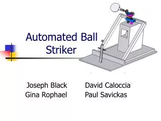
Automated Ball Striker
290 likes | 422 Vues
This presentation outlines the development of an Automated Ball Striker designed for training ping pong players. Inspired by previous models, the system features a mechanism to launch a ping pong ball vertically at varying heights, accompanied by a trajectory tracking controller. Based on comprehensive specifications, it utilizes advanced control design, modeling, and image processing techniques. Results demonstrate consistent accuracy in striking and trajectory generation. The presentation concludes with improvements to enhance launcher performance and target aiming capabilities.

Automated Ball Striker
E N D
Presentation Transcript
Automated Ball Striker Joseph Black David Caloccia Gina Rophael Paul Savickas
Presentation Outline • Motivation • Objective • Specifications • Design Approach • Results • Assessment • Conclusion
Motivation • Extension of the Ping Pong Shooter from Team 2 of Spring 2005 • Inspiration: to develop training equipment for ping pong players.
Objectives To strike a vertically launched ping pong ball. • Launch a ping pong vertically at various heights • Visually locate the launched ping pong ball • Process data to determine ball’s position and velocity • Develop trajectory for paddle’s motion • Design a controller to track the desired path
Specifications Step response: • Steady State Error 0.195% • Percent Undershoot 12.58% • Rise Time 0.43 s • Settling Time 1.43 s Other Specifications: • Range of Motion (Pan) -80°to +100° • Range of Motion (Tilt) 0°to +90° • Payload 200 grams • Noise Tolerance 95% • Weight of the System is ~1Kg • Commercial Cost $2462.75 • Speed is 8rad/sec for pan and for tilt 10rad/sec • Images processing rate 30 frames/second • Sampling time for the controller 10 micro sec
Design Approach • Modeling • Control Design • Launcher • Vision • Physics Model • Trajectory Generation • Integration
Modeling • General Equation of Motion • Disconnect between model and system • A simpler model was pursued
Modeling • Simplified Equation of Motion • Steady State • Friction Identification • Transient Response • Inertia
Friction Identification Viscous Friction = .0087 NmS/rad Coulomb Friction = .0141 Nm
Model Validation • Open loop response
Model Validation • Closed loop response • Differences between model and system • The final model was useful in understanding the system, but control design was done on the actual system.
Control Design • Control applied using the FPGA PID block in LabVIEW. • The PID for set point control with sampling of 100 microseconds, 512 proportional for pan and tilt , 3/128 integration for pan and 1/128 for tilt. • Swing controller pan 10 microsecond sampling, proportional 1792 , derivative 7/128, derivative control may not have much affect with such a high sampling rate.
Launcher • Final Design • Ball Support • Multiple Balls • Performance • Launch Height • Verticality
Vision • Collect frames at 30 frames per second, threshold the individual images and filter out small objects, to remove dust and the black balls reflecting light back to camera. • Check for ball in frame, first time records the position and time of image after 2nd image of ball subtracts position and time from previous image to determine velocity
Vision • Used LabVIEW Vision Assistant to make calibration information image from a image of a dot matrix in the plane of the launch, with black dots at a known distance from each other fed to LabVIEW.
Physics Model • Ball Motion • 1D Motion • Initial Velocity • Position/Time Calculations • Air Resistance • Time Until Swing
Trajectory Generation • The choice of start and end positions • Development in Trajectory • Ability to choose between trajectories
Integration • Physical Integration • Base, Launcher, Webcam, Pan-Tilt • Software (LabVIEW) • Physics Model • Image Processing
Integration • A laptop is used as a host to connect to the web cam and retrieve images of the ball and calculate position, velocity and time to swing information from physics model. • Laptop communicates to begin the swing to the CRIO using VI Server, breaking the CRIO out of a set point loop into the swing signal loop. • The CRIO was used as a Real Time system to control the FPGA and to send the swing path and set points to FPGA at 1 kHz. The FPGA is used for control of the system and monitoring the position and velocity
Integration • Testing • Subsystem • Overall System • Uncertainty • Launcher • Physics Model • Swing Time • Strike Zone
Results • Probability of successful striking • Demonstration Video
Assessment • Ball Launching • Inconsistent launch • Vision/Physics Model • Reliable for successful launches • Trajectory Generation and Tracking • Accurate tracking of trajectory • Overall Success
Conclusion • Recommendations for improvement • Improvements to launcher would greatly benefit the rest of the system • Ability to aim ball toward target zones • State-space control