Heat Transfer from Protuberances and Simulated Ice Accretion Roughness Elements
190 likes | 305 Vues
This study investigates the impact of surface roughness elements on heat transfer during aircraft icing, a critical flight safety concern. By analyzing local heat transfer coefficients and utilizing a novel Mylar application technique, we examined the effects of metallic protuberances on heat transfer rates. Our experiments included small and large test plates with various roughness elements to measure apparent enhancement in heat transfer and flow characteristics. Findings indicate successful maintenance of a constant heat flux boundary condition with implications for future research in aerodynamics and ice formation prevention.

Heat Transfer from Protuberances and Simulated Ice Accretion Roughness Elements
E N D
Presentation Transcript
Heat Transfer from Protuberances and Simulated Ice Accretion Roughness Elements Scholars Day 04/20/2009 Steven Mart Mentor: Dr. Stephen T. McClain
Outline • Aircraft Icing & Henry et al. • Small Test Piece • New Mylar Application Technique • Results & Conclusions • Large Test Plate • Construction • Results • Apparent Enhancement of Elements • Flow Characteristics • Conclusions & Improvements • Future Research
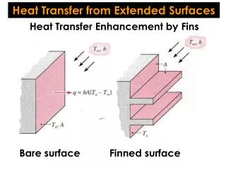
The Icing Problem • Aircraft icing is a serious flight safety concern and is not completely understood • Initial heat transfer influences how ice formations grow on aircraft surfaces • By analyzing the local heat transfer coefficient we can better understand how ice develops • Continuation of research by Henry et al. • Used gold deposited Mylar film to study the local heat transfer
Gold Deposited Mylar Film • Thin, uniform coating of gold over Mylar • Applied by vacuum sputter deposition • Highly susceptible to degradation and contamination (scratches, oils, etc.) • Used to apply a constant heat flux boundary condition
New Application Method • Need to mount metallic roughness elements to gold Mylar • Traditional application orients film gold-side up • Mounting high thermal conductivity elements creates local hot spots • Negates the constant heat flux boundary • Needed a way to mount elements without disrupting the boundary condition
New Application Method (cont’d.) • Developed new gold-side down orientation • Elements attached to non-conductive side • Maintains constant flux boundary condition • Requires consideration of additional heat transfer modes • Mylar conduction • Plexiglas conduction
Test Piece Profiles • 3.9% variation within central region of plate • Encouraging due to small size of Mylar used
Small Test Piece Conclusions • New mounting procedure verified as a viable mounting solution • Constant flux boundary condition still maintained • Allows for the mounting of roughness elements • Transitioned into creation and testing of full scale test plate
9.53 mm Steel Roughness Element 5.0 mm Plastic Roughness Element 9.53 mm Plastic Roughness Element Test Plate Construction
Testing & Data Acquisition IR Camera Test Plate IR Temperature Gun
Test Plate Results • Investigated apparent enhancement (AE) of elements • Indicates how much heat transfer has increased due to the presence of protuberances vs. unperturbed regions • Not a true enhancement measurement but still useful • Compared to data of Henry et al. • Also analyzed flow characteristics
AE for Large Plastic Element AE for Large Steel Element AE for Small Plastic Element • Material properties and size influence AE • Increasing enhancement for increasing velocity • Vortices • Flow Separation
AE vs. Reynolds Number 1 mps 5 mps 10 mps 20 mps
Flow Characteristics Large Steel Element Large Plastic Element • Flow from bottom to top, increasing left to right • Flow separation and reattachment • Again, influence of material and size Small Plastic Element
Flow Characteristics (cont’d.) Large Plastic Element • Greater and more uniform temperature profile for steel due to its conductive properties • Effects of separation vortices visible at high speeds • Elongation of profiles also visible Large Steel Element Small Plastic Element
Conclusions & Recommendations • Apparent enhancement results in general agreement with those of Henry et al. • Need to compare data to flat plate correlations • New higher amperage power supply needed • Eliminate power issues • Needed for higher velocity tests • Automation of voltage, current and pressure measurements
Future Studies • Tests at higher flow velocities • Influence of turbulent flow on AE • Accelerating/Decelerating Flow • Large roughness element distribution (400+) • Plastic Element Distribution • Steel Element Distribution
Acknowledgements • Dr. Stephen McClain • Dr. Kenneth Van Treuren • Dr. Ian Gravagne • Mr. Ashley Orr • Gilbert Narvaez III • John Miller [1] Henry, R. C., Hansman, R. J., Breuer, K. S., “Heat Transfer Variation on Protuberances and Surface Roughness Elements”, Journal of Thermophysics and Heat Transfer, Vol. 9, No. 1, March 1995.
Thank You Questions?