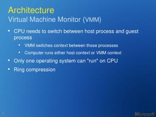
Machine Architecture
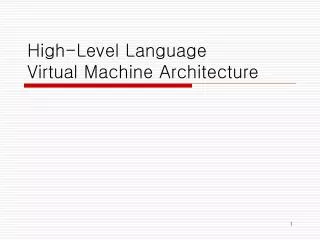
Machine Architecture. Machine Architecture. Secondary Storage. Input Device. I/O Ports. I/O Controller. I/O Controller. Main Memory. Processor. Address Bus. Data Bus. Control Bus. This diagram shows the basic structure of a computer system, know as the machine’s architecture :.


Machine Architecture
E N D
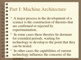
Presentation Transcript
Machine Architecture Secondary Storage Input Device I/O Ports I/O Controller I/O Controller Main Memory Processor Address Bus Data Bus Control Bus This diagram shows the basic structure of a computer system, know as the machine’s architecture:
Key Components (1) Processor: The central component of the computer, which is used to execute the instructions in a program. Main Memory: Storage locations which are directly addressable by the processor. Each memory location can be identified by a unique address. Secondary Storage: Additional storage, outside of the main memory, which can be used to store data whilst the computer is turned off.
Key Components (2) I/O Controller: A device that passes commands and control signals from the computer’s system bus to attached peripherals, converting the format of these as required. I/O Port: The part of the I/O Controller through which the connection to an I/O device is made.
Buses (1) The components of the computer are connected together by three buses, which together are known as the system bus. A bus is a collection of parallel wires or tracks which are used to transfer data between independent components of a computer by passing signals. The number of parallel wires that a bus is made up of is known as the bus width. Typical bus widths are 32, 64 and 128 bits. Buses can be unidirectional (only carry data in one direction) or bidirectional (work in both directions).
Buses (2) The three buses that make up the system bus are: Address Bus: Used by the processor to send addresses to the main memory. Addresses indicate which location data should be written to or read from. Unidirectional from processor to other components. Data Bus: Used to transfer data between the processor and main memory or other devices connected to I/O controllers. Bidirectional. Control Bus: Carries control signals from the processor to other devices and returns status signals from these devices to the processor. Bidirectional.
Components of the Processor The four main components of the processor are: Arithmetic and Logic Unit (ALU): Performs calculations and logical operations such as comparisons and masking. Control Unit: Manages instruction execution by producing the necessary control signals to activate, in the correct order, the hardware components of the processor that are required to carry out an instruction. Registers: Fast memory locations which are located on the processor. Clock: Generates timing pulses which are used to sequence the fetch-execute cycle.
Main Memory The main memory consists of storage locations which are directly addressable by the processor. Each memory location has a unique address, which is a number. The contents of any memory location can be read from/written to by providing the main memory with its address. Therefore, this type of memory is sometimes known as addressable memory. It is also known as Random Access Memory (RAM) (alternative is associative memory)
The CPU • Different authors use the term Central Processing Unit (CPU) in different ways: • Some describe the CPU as being comprised of the processor, main memory and associated buses. • Others use CPU as an alternative name for the processor on its own. • The AQA A Level Computing specification interprets the CPU as comprising the processor, main memory and buses. • The CPU includes all of the components that are needed to fetch, decode and execute instructions, writing the results back to the main memory.
Processor Performance Factors (1) The performance of a processor is affected by three important factors: Clock Speed: How frequently the clock that controls the fetch execute cycle ticks. Word Length: The number of bits that the processor can manipulate in one operation. Bus Width: The number of parallel wires that a bus is composed of. The width of the address and data buses are independent.
Stored Program Concept • Modern computers use the stored program concept. • The stored program concept is that: • machine code instructions are stored in main memory, • these are fetched and executed serially, • by a processor that performs arithmetic and logical operations. • The concept was introduced by John von Neumann. • Previously, “programs” were entered into a computer by techniques such as setting switches and plugging patch leads into panels. • The concept can be seen earlier in Alan Turing’s development of the Universal Turing Machine.
The Fetch-Execute Cycle The Fetch-Execute cycle is the basic operation cycle of a computer. The cycle is repeated over and over again from the moment a computer is turned on until it is turned off. Each time that the cycle is iterated, a single machine code instruction if fetched from main memory, decoded and executed. The result (output) of an instruction is usually stored into a general purpose register but could also be written back to main memory.
F-E Cycle Stages The Fetch-Execute cycle has three stages: Fetch: The instruction to execute is retrieved from the main memory. Decode: The op-code part of the instruction is examined to determine which parts of the CPU must be used to carry out the instruction. Execute: The appropriate hardware components of the CPU are used to carry out the instruction.
F-E Cycle Registers • The Fetch-Execute cycle makes use of some specific purpose registers on the processor: • Program Counter (PC): Stores the address in main memory of the next instruction to execute. • Memory Address Register (MAR): Stores the address in main memory of the location that the processor is currently reading data from or writing data to. • Memory Buffer Register (MBR): Temporarily stores the word of data that is currently being transferred between the processor and the main memory. • Current Instruction Register (CIR): Stores the instruction that is currently being executed by the processor whilst it is decoded and executed.
F-E Cycle Notation The steps involved in the Fetch-Execute cycle are often described in register transfer notation. This has the format: Register / Storage Location Value e.g. MAR [PC] means that the contents of the Program Counter are copied into the Memory Address Register The symbols [] are used to indicate the contents or a register or storage location.
F-E Cycle Animation (1) The animation on the next slide shows one iteration of the fetch-execute cycle, to carry out the instruction stored in memory location 104. The animation focuses in most detail on the fetch stage of the cycle as this stage is the same for all instructions.
F-E Cycle Animation (2) 1 MAR [PC] (Contents of Program Counter transferred to MAR) (a) PC [PC] + 1 (Increment contents of Program Counter) (b) MBR [Memory]addressed (Contents of addressed memory location loaded into MBR) 2 Simultaneous • Memory address transferred along address bus to main memory. CIR [MBR] (Transfer contents of Memory Buffer Register into Current Instruction Register) • Contents of addressed location looked up in main memory. 3 • Looked up value transferred to processor along data bus. Processor Main Memory Address Content 100 01110101101 11010101102 00101000103 11011001104 10000101105 10101101106 01001101 PC MAR 4 Address Bus Decode instruction +1 105 104 104 104 5 CIR MBR Data Bus Execute instruction 104 10000101 10000101 10000101 10000101
F-E Cycle Decode Stage (1) instruction 10000101 1000 0101 op-code operand During the decode stage, the control unit splits the instruction in the CIR into two parts: Op-code: The binary pattern which identifies the instruction to be carried out e.g. add, or, branch. Operand: The data that the instruction will operate on.
F-E Cycle Decode Stage (2) The operand could be a number such as 5, which the instruction should use directly. Alternatively it might be the address in main memory where the data to use is stored. How to interpret the operand will depend upon the addressing mode that the instruction is using. Instructions may have zero, one or more operands.
F-E Cycle Execute Stage (1) What happens in the execute stage of the cycle is determined by the op-code of the instruction that is being executed. The op-code will determine which circuitry within the processor should be used to carry out the instruction. Temporary results and the final result of executing instructions are usually stored in registers instead of main memory as registers can be accessed much more quickly. Modern computers have many general purpose registers, but it can be convenient to think of a simplified model of a computer with just one general purpose register, known as the accumulator.
F-E Cycle Execute Stage (2) The example below shows the execute stage for an ADD instruction that adds the value in a specified memory location onto the current value in the accumulator register, storing the result in the accumulator.
F-E Cycle Execute Stage (3) After an instruction has been executed, the contents of a special purpose register known as the status register are updated. Each bit of the status register is known as a flag and has a specific purpose. Some example status register bits are: The status register stores information about the result of previous operations as these may affect future operations.
Machine Architecture Solution Secondary Storage Output Device I/O Controller I/O Controller Main Memory Processor Address Bus Control Bus Data Bus Q1) Correctly labelled machine architecture:
Buses Solution Q2) (a) Bus: A bus is a collection of parallel wires or tracks which are used to transfer data between independent components of a computer by passing signals. (b) Unidirectional or bidirectional:
Processor Components Solution Q3) Purposes of the parts of the processor: (a) Arithmetic and Logic Unit (ALU): Performs calculations and logical operations such as comparisons and masking. (b) Control Unit: Manages instruction execution by producing the necessary control signals to activate, in the correct order, the hardware components of the processor that are required to carry out an instruction.
Registers Solution Q4) • Program Counter (PC): Stores the address in main memory of the next instruction to execute. • Memory Address Register (MAR): Stores the address in main memory of the location that the processor is currently reading data from or writing data to. • Memory Buffer Register (MBR): Temporarily stores the word of data that is currently being transferred between the processor and the main memory. • Current Instruction Register (CIR): Stores the instruction that is currently being executed by the processor whilst it is decoded and executed. • Status Register: Stores information about the result of the previous operation which may be required for future operations.
Fetch Stage Solution Simultaneous Q5) (a) RTN for the fetch stage: MAR [PC] PC [PC] + 1 MBR [Memory]addressed CIR [MBR] (b)How the buses and memory are used: Memory address of instruction to execute is copied into MAR and then transmitted along the address bus to main memory. The main memory looks up the contents of the specified address and returns the instruction in this address along the data bus to the processor, where it arrives in the MBR.
Op-code Solution Q6) Purpose of the op-code: Op-code is: The binary pattern which identifies the instruction to be carried out e.g. add, or, branch. Op-code used to: Determine which circuitry within the processor should be used to carry out the instruction.