Download
1 / 20
200 likes | 323 Vues
The foundation of modern computing relies on machine architecture, focusing on data storage and representation. This process not only involves storing bits in various forms, such as main memory and mass storage, but also addressing coding information effectively. Key topics include the binary system, representation of integers and fractions, the significance of memory cells, and data compression techniques. Whether it's through the use of flip-flops for bit storage or the complexities of floating-point notation, understanding these concepts is crucial for advancements in technology and for addressing challenges such as communication errors and storage limitations. ###

E N D
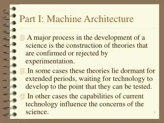
Part I: Machine Architecture • A major process in the development of a science is the construction of theories that are confirmed or rejected by experimentation. • In some cases these theories lie dormant for extended periods, waiting for technology to develop to the point that they can be tested. • In other cases the capabilities of current technology influence the concerns of the science.
Ch. 1 Data Storage • Storage of bits. • Main memory. • Mass storage. • Coding information for storage. • The binary system. • Storing integers. • Storing Fractions. • Communication errors.
Storage of bits • Today’s computers represent information as patterns of bits. • Gates are devices that produce the output of a Boolean operation when given the operation’s input values. • A flip-flop is a circuit that has one of two output values (i.e., 0 or 1), the output will flip or flop between two values under control of external stimuli.
Storage of Bits • A flip-flop is ideal for the storage of a bit within a computer (Fig 1.3 and 1.4). A flip-flop loses data when its power is turned off. • Cores, a donut-shaped rings of magnetic material, are obsolete today due to their size and power requirements. • A magnetic or laser storage device is commonly used when longevity is important. • Hexadecimal notation (Fig. 1.6).
Main Memory • Cells - a typical cell size is 8 or called byte. • MB = 1,048,576 (2 ** 20) bytes, KB and GB. • Address is used to identify individual cells in a main memory. • Random access memory (RAM). • Read only memory (ROM). • Most significant bit (MSB) and least significant bit (LSB).
Mass Storage • Secondary memory. • Storing large units of data (called files). • Mass storage systems are slow due to mechanical motion requirement. • On-line Vs. off-line operations.
Mass Storage • Mass StorageDisk storage. • Floppy disk and hard disk • Track, sector, seek time, latency time (rotation delay), access time, transfer time • Milliseconds Vs. nanoseconds • Compact disks and CD-ROM. • A single spiral track • Tape storage.
Mass Storage • Physical Vs. logical records. • Buffer. • Main memory and mass storage. • Main memory, magnetic disk, compact disk and magnetic tape exhibit decreasing degrees of random access to data.
Representing Text • American Standard Code for Information Interchange (ASCII) - 8-bit codes. • Appendix A • Figure 1.12 • Unicode - 16-bit codes; allow to represent most common Chinese and Japanese symbols. • International Standards Organization (ISO) - 32-bit codes.
Representing Numeric Values • Using 16 bits, the largest number we can store in ASCII is - • Binary notation (Figures 1.14 and 1.16). • Given 16 bits, the largest number we can store is - • A particular value may be represented by several different bit patterns; a particular bit pattern may be given several interpretations.
Representing Images • Bit map representation • An image is considered as a collection of pixel • a pixel can be black or white, represented by a bit • a pixel can be a color, represented by three bytes • A typical photograph consists of 1280 rows of 1024 pixels • requires several megabytes of storage • image compression • Vector representation provides a means of scaling.
The Binary System • Binary addition. • Fractions in binary. • Radix point (same as decimal point in decimal notation) • Figure 1.18 • Example of addition
Storing Integers in Computers • Two’s complement notation. • Figure 1.19 • Sign bit • How to decode a bit pattern? • Addition in two’s complement notation. • Addition of any combination of signed numbers can be accomplished using the same algorithm • simplify circuit design • Figure 1.21
Storing Integers in Computers • Overflow problem. • Limit to the size of the values that can be represented • 5 + 4 = -7 • Addition of two positive (negative) values appears to be negative (positive) • Excess notation. • Figures 1.22 and 1.23 • excess 8 (4) notation for bit patterns of length 4 (3)
Storing Fractions in Computers • Floating-point notation. • Sign bit, exponent field, mantissa field • Exponent expressed in excess notation • 01101011 = - • 1.125 = - • 0.375 = - • All nonzero values have a mantissa starting with 1
Storing Fractions in Computers • Round-off errors. • Mantissa field is not large enough • 2.625 = - • Order of computation • 2.5 + 0.125 + 0.125 = - • Nonterminating representation • 0.1 = - • change the unit of measure from dollar to cent for a dime
Data Compression • Run-length encoding. • A bit pattern consists of 253 1’s, followed by 118 0’s • Relative encoding. • Each data block is coded in terms of its relationship to the previous block
Data Compression • Frequency-dependent encoding. • More frequently used characters are represented by shorter bit patterns • Huffman codes • Adaptive dictionary encoding. • Lempel-Ziv encoding • ABAABQB (5,4,A) (0,0,D) (8,6,B)
Data Compression • GIF. • Each pixel is represented by a single byte • JPEG. • Human eyes are more sensitive to changes in brightness than color • Each four-pixel block is represented by six values rather than 12 values • MPEG.
Communication Errors • How can you make sure the information you received is correct? • Coding techniques for error detection and correction. • Parity bits. • Error-correcting codes. • Figures 1.28 and 1.29 • Hamming distance of at least five is able to detect up to - errors and correct up to - errors