Leakage reduction techniques
Leakage reduction techniques. 2006. 10. 30. Three major leakage current components 1. Gate leakage ; ~ Vdd 4 2. Subthreshold ; ~ Vdd 3 3. P/N junction BTBT current. Circuit techniques to reduce leakage. Design time techniques DTCMOS(dual threshold CMOS)


Leakage reduction techniques
E N D
Presentation Transcript
Leakage reduction techniques 2006. 10. 30
Three major leakage current components 1. Gate leakage ; ~ Vdd4 2. Subthreshold ; ~ Vdd3 3. P/N junction BTBT current
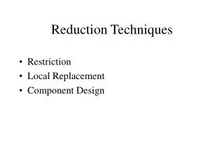
Circuit techniques to reduce leakage • Design time techniques • DTCMOS(dual threshold CMOS) • Multiple power supply voltages (islands) • Run time techniques • Reducing standby leakage • Using transistor stacks • MTCMOS ; sleep transistor • VTCMOS • Reducing active leakage • DVS ; dynamic Vdd scaling • DVTS ; dynamic Vth scaling
Increasing Vth followed by upsizing yields similar on current with much less leakage current at the cost of switching power and chip area. Ids Vgs
Transistors on during precharge period is a non-critical path and is given high Vth.
If Vs is raised, there are three mechanisms leading to the reduction of drain current, i.e., Vds, Vgs and Vth
Input vector control, e.g., ABC=111 and 000 yields lowest leakage current for 3-in NOR and 3-in NAND. Explain why. As gate leakage becomes dominant over subthreshold, ABC=100 can yield less leakage than ABC=000. Explain why.
MTCMOS ; reduces leakage during sleep mode only, at the cost of area and delay. Only NMOS may be used.
In Stby mode Clk=1, Sleep=1 That prevents continuous supply of leakage current to GND through node 1, and leakage current to GND through node 2.
VTCMOS ; (a) Body (and N-well) biasing technique, Z(ero)BB or F(orward)BB for speed up & reducing SCE in active mode , while RBB in stby mode. Routing grid for body biasing adds area. 103 reduction in 0.35 um technology. Effectiveness of RBB to lower Ioff decreases as IBTBT increases exponentially due to HALO doping. (b) Source biasing instead of p-substrate. Substrate is shared between Target and control circuitry. VNEWLL is raised to conserve the stored charge if necessary. Reducing VDS thereby further decreases leakage Current thru less DIBL which raises Vth.
DVS (Dynamic Voltage Scaling) consists of • Processor operating in wide voltage/frequency range • Regulation loop (F-V) generating min vtg needed for the given freq. • Operating System that computes desired clock frequency
DVTS vs. DVS Similar effect when leakage is dominant over switching power.
Merits & Issues of DVTS (Candidate topic for individual project) • Simple hardware ; • charge pump is used as current demand is low instead of buck converter which is used in DVS • Transition energy overhead • Substrate noise ; • due to absence of inductor, charge pumps can generate noise • Process complexity
Leakage reduction is especially important in cache As each cell is in inactive state most of the time.
Five different Low-leakage SRAM cell techniques in Table 13.3 • Things for further study (research candidate) • Re-evaluation of each different technique in terms of their effect on each different leakage component, i.e., subthreshold, direct tunneling gate oxide, BTBT leakage • How the read/write delay is affected by each low leakage technique • Transition latency/energy overhead • Impact on cell reliability incl. SER