Leakage Reduction in SRAM Utilizing Power Gating
220 likes | 615 Vues
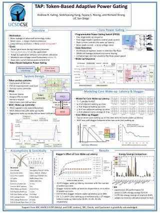
Leakage Reduction in SRAM Utilizing Power Gating. Kyle Craig Yousef Shakhsheer. Objectives. To implement a leakage reduction energy standby mode that maintains state for SRAM, utilizing headers and footers. Current power-gating methods can cause bit cells to lose state. BC. Proposed Method.

Leakage Reduction in SRAM Utilizing Power Gating
E N D
Presentation Transcript
Leakage Reduction in SRAMUtilizing Power Gating Kyle Craig Yousef Shakhsheer
Objectives To implement a leakage reduction energy standby mode that maintains state for SRAM, utilizing headers and footers. Current power-gating methods can cause bit cells to lose state.
BC Proposed Method • Add headers/footers to SRAM bitcells/columns • Put the these bitcells/colums into sleep mode • All headers/footers turned off • Ability to maintain data in the cell, and save energy .
Approach • Tested settling voltage • Figured out DRV • Assumed virtual VSS values and calculated the min VDD needed • Static Noise Margins (butterfly plots) • Test for functionality • Sensing Circuit
Settling Voltage VDDv 1BC VDDv/VSSv 64BC VSSv 1BC
Settling Voltage TT SS
Settling Voltage Header/Footers min sized, 4096 shared BC
Test for Functionality • Normal Operation • Transitioning
Sensing Circuit v1 Very Long ~5X min L Very Wide ~7X min W
Sensing Circuit • Why Large W and L? • Need to make left NMOS (VSSv) stronger than the right NMOS • Gate voltage of VSSv will always be less than VDDv • Large width compensates for lower gate voltage. • Sizing can be tweaked to change the ΔV that it triggers on.
VDDv VSSv Out
Enable Out VDDv VSSv Enable Sensing Circuit v2
Sensing Circuit • Enable is clocked • Output and Enable are NANDed together • Produced an overall out of 0 when it fires for a period of time
VDDv VSSv NAND Out
Sensing Circuit v1 vs v2 • V1 • Less complicated to control • Lower area • Limited sensing scope • More Energy • V2 • Lower Energy • Can handle wider scope of sensing since it is reset by the keeper PMOS
Results Compare to 62 pJ!