Guarded Power Gating in a Multi-core Setting
250 likes | 428 Vues
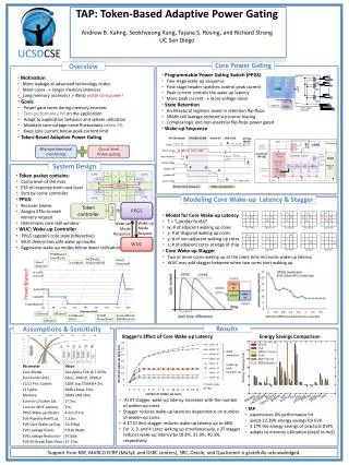
Guarded Power Gating in a Multi-core Setting. Niti Madan , Alper Buyuktosunoglu , Pradip Bose, IBM T.J.Watson June 2010. Murali Annavaram USC. Outline. Motivation Queuing Model based Methodology Results Conclusions and Future Work. Power Management through Power Gating .

Guarded Power Gating in a Multi-core Setting
E N D
Presentation Transcript
Guarded Power Gating in a Multi-core Setting NitiMadan, AlperBuyuktosunoglu, Pradip Bose, IBM T.J.Watson June 2010 MuraliAnnavaram USC
Outline Motivation Queuing Model based Methodology Results Conclusions and Future Work
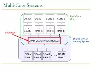
Power Management through Power Gating • Use header or footer transistor to power-gate the idle circuit • Apply “sleep” to header or footer => turn off voltage • Can be applied at unit-level (intra-core or small-knob) • Can be applied at core-level (per-core or big-knob) Vdd Sleep Virtual Vdd . . Logic Block . .
Predictive Power Gating Energy • Power-gating Algorithms are predictive by nature • Frequent mis-predictions can burn more power than save • Break-even point dependent upon block-size and tech parameters • Guard mechanism proposed for unit-level power gating algorithms by Lungu et al. (ISLPED’09) • Concern for per-core power gating algorithms as breakeven point is much higher for cores Break-even point Cumulative Energy Savings Energy Overhead 0 Decide to power gate Wake-up Ex. break-even point = 10 cycles Decide to Power Gate …10100 0000000000… Correct prediction => save power Decide to Power Gate …10100 001…………. Anita Lungu,Pradip Bose, AlperBuyuktosunoglu, Daniel Sorin,”Dynamicpower gating with quality guarantees”. ISLPED ‘09
Power Gating Scenarios Core 1 Core 2 time Core 3 Core 4 time • Exploiting the two dimensions of utilization to power-gate idle units or cores • System Utilization (OS perspective) triggers the big-knob • Resource Utilization (Core’s perspective) triggers the small-knob • Do we PG cores or execution units or both? • How can we maximize power-savings opportunities provided by both the small and big knobs ? (a) Baseline 4-core system (b) Folded 2-core system
Goals of this study Explore the trade-offs between unit-level/small-knob power gating algorithms and per-core/big-knob power gating algorithms for a range of latencies/parameters Leverage analytical models for early-stage evaluation A case for guard mechanism for per-core power-gating • SriramVajapeyam, Pradip Bose
? Customers Arrivals Queue Departures Server(s) Queuing Theory Based Analytical Model • Representation of Multi-processor workloads as a Queuing system • Cores are servers • Processing tasks are customer requests • Tasks are processed in FCFS order • Queuing system tracks average customer waiting time, service time and server utilization • Evaluate our power-management policies using C++ based Queuing model simulator: “QUTE”
Overview of QUTE Framework • Simulation of Queuing Models (G/G/N/k/inf/FCFS) • Faster than cycle-accurate simulations • Easy to explore design-space early on • Statistical Workload GenerationParameters: • Task Arrival Times: Exponential Distribution • Task Lengths: Normal/Exponential/Uniform Distributions • Evaluation Metrics: • Performance:Average response time • Power: Average number of cores switched on • Other Stats: Server utilization, variance in service demand etc.
Task arrival QUTE Framework (arrival rate distribution using random number generator) . . FIFO Task Queue (service time or task Length statistical distribution) C1 C3 C4 …….. C2 (all cores queue back the task at the end of a time slice)
Big Knob Modeling Implemented a simple Idleness-triggered heuristic: Set Idleness Threshold (say to 0.5 msec) Every 0.5 msec (i.e. the idleness threshold), Scan all cores Identify cores idle for > idleness threshold Switch off all such cores (except, make sure there is always at least one core ON, either free or active) When a task arrives at the head of the task queue: If there is no free core, If there is a switched-off core, switch it ON
Small Knob Modeling Cannot directly simulate workload phases Each core can have N power states 2 states for this version : nominal power state and low power state (75% power) Generate statistical distribution (Gaussian) of each power state duration Each task always starts in the nominal power state Switch between power states in a given time-slice Parameters: Nominal (Hi) and Low (Lo) power state means, Transition overhead
Simulation Parameters ρ= λ/ N*µ
Outline Problem Background Methodology: Queuing Model Results Conclusions and Future Work
Big Knob Results • CT controls the degree of power-savings (up to 34%) • OnLat controls the performance loss(up to 5%)
Idle-Time Durations Histogram CT Number of durations Idle-time Duration (us)
Small Knob Results System_Power = Num_cores x (%time_in_Hi_state + F x %time_in_Lo_state) x P where F = 0.75 for this analysis • Power-savings dependent upon workload behavior • Short phases increases number of transitions and overhead • Transition overhead tolerable for our assumptions Performance Loss % Transition Overhead (us)
Hybrid Model Results (Big + Small Knob) • High ILP workloads – Big knob is most helpful • Low ILP workloads – Small knob helpful for even lower utilization Low ILP Workload High ILP Workload
A Case for Guard Mechanism for Multi-core Power Gating • Depending upon workload characteristics, Per-core power gating heuristics are prone to mis-predictions and dissipating more power • Aggressive power-gating heuristics are also increase the performance overhead of mis-prediction (e.g. Lower CT )
Observations In a fully loaded system, the small knob is helpful In a lightly loaded system, the big knob is most useful In the intermediate loaded system, the big knob is useful to have but the usefulness of the small knob depends upon the workload characteristics Lower ILP or low resource utilization workloads are benefited by the small knob Small knob is a useful feature to have regardless of system load if we can implement power state with lower power factor Current power factor is conservative (0.75)
Future Work Improve methodology by supporting real server utilization traces Evaluate a system with multiple P-states and DVFS Architect guard mechanisms for the per-core power gating algorithms Design implementation of a hybrid PG system
Two Level Power Gating Algorithms (Lungu et al. ISLPED'09) Observations: Correctness requirement of power saving schemes (efficiency-wise): save power Single level idle prediction algorithms can behave incorrectly and waste power Proposed Idea: Add second level monitor to control enabling of power gating scheme Improve efficiency of power wasting cases without degrading power saving of common case Per-core power-gating algorithms also rely on such predictive schemes and will require guard mechanisms Cost of misprediction is higher in per-core power-gating Level 2: Monitor & Control Estimate Power Savings No Enable = 0 > 0 Yes Enable = 1 Efficiency Counters Enable On Off_U Off_C Cnt1++ Cnt2++ Level 1: Actuate Off_U: Power gated, uncompensated Off_C: Power gated, compensated