Particle Detectors
520 likes | 730 Vues
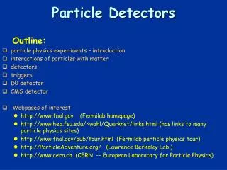
Particle Detectors. particle physics experiments – introduction interactions of particles with matter detectors triggers D0 detector CMS detector Webpages of interest http://www.fnal.gov (Fermilab homepage)

Particle Detectors
E N D
Presentation Transcript
Particle Detectors • particle physics experiments – introduction • interactions of particles with matter • detectors • triggers • D0 detector • CMS detector • Webpages of interest • http://www.fnal.gov (Fermilab homepage) • http://www.hep.fsu.edu/~wahl/Quarknet/links.html (has links to many particle physics sites) • http://www.fnal.gov/pub/tour.html (Fermilab particle physics tour) • http://ParticleAdventure.org/ (Lawrence Berkeley Lab.) • http://www.cern.ch (CERN -- European Laboratory for Particle Physics) Outline:
Particle physics experiments • Particle physics experiments: • collide particles to • produce new particles • reveal their internal structure and laws of their interactions by observing regularities, measuring cross sections,... • colliding particles need to have high energy • to make objects of large mass • to resolve structure at small distances • to study structure of small objects: • need probe with short wavelength: use particles with high momentum to get short wavelength • remember de Broglie wavelength of a particle = h/p • in particle physics, relativistic effects important; mass-energy equivalence plays an important role; in collisions, kinetic energy converted into mass energy;
p p How to do a particle physics experiment • Outline of experiment: • get particles (e.g. protons, antiprotons,…) • accelerate them • throw them against each other • observe and record what happens • analyze and interpret the data • ingredients needed: • particle source • accelerator and aiming device • detector • trigger (decide what to record) • recording device • sufficiently many people to: • design, build, test, operate accelerator • design, build, test, calibrate, operate, and understand detector • analyze data • lots of money to pay for all of this
About Units • Energy - electron-volt • 1 electron-volt = kinetic energy of an electron when moving through potential difference of 1 Volt; • 1 eV = 1.6 × 10⁻¹⁹Joules = 1.6 × 10⁻¹⁹ W•s • 1 kW•hr = 3.6 × 10⁶ Joules = 2.25 × 1025 eV • mass - eV/c2 • 1 eV/c2 = 1.78 × 10-36kg • electron mass = 0.511 MeV/c2 • proton mass = 938 MeV/c2 • momentum - eV/c: • 1 eV/c = 5.3 × 10⁻²⁸kg m/s • momentum of baseball at 80 mi/hr 5.29 kgm/s 9.9×1027eV/c
WHY CAN'T WE SEE ATOMS? • use accelerated (charged) particles as probe, can “tune” wavelength by choosing mass m and changing velocity v • “seeing an object” • = detecting light that has been reflected off the object's surface • light = electromagnetic wave; • “visible light”= those electromagnetic waves that our eyes can detect • “wavelength” of e.m. wave (distance between two successive crests) determines “color” of light • wave hardly influenced by object if size of object is much smaller than wavelength • wavelength of visible light: between 410-7m (violet) and 7 10-7 m (red); • diameter of atoms: 10-10m • generalize meaning of seeing: • seeing is to detect effect due to the presence of an object • quantum theory “particle waves”, with wavelength 1/(m v) • this method is used in electron microscope, as well as in “scattering experiments” in nuclear and particle physics
Detectors • Detectors • use characteristic effects from interaction of particle with matter to detect, identify and/or measure properties of particle; has “transducer” to translate direct effect into observable/recordable (e.g. electrical) signal • example: our eye is a photon detector; (photons = light “quanta” = packets of light) • “seeing” is performing a photon scattering experiment: • light source provides photons • photons hit object of our interest -- some absorbed, some scattered, reflected • some of scattered/reflected photons make it into eye; focused onto retina; • photons detected by sensors in retina (photoreceptors -- rods and cones) • transduced into electrical signal (nerve pulse) • amplified when needed • transmitted to brain for processing and interpretation
Particle interactions with matter • electromagnetic interactions: • excitation • ionization • Cherenkov radiation • transmission radiation • bremsstrahlung • photoelectric effect • Compton scattering • pair production • strong interactions: • secondary hadron production, • hadronic showers • detectors usually have some amplification mechanism
Interaction of particles with matter • when passing through matter, • particles interact with the electrons and/or nuclei of the medium; • this interaction can be weak, electromagnetic or strong interaction, depending on the kind of particle; its effects can be used to detect the particles; • possible interactions and effects in passage of particles through matter: • excitation of atoms or molecules (e.m. int.): • charged particles can excite an atom or molecule (i.e. lift electron to higher energy state); • subsequent de-excitation leads to emission of photons; • ionization (e.m. int.) • electrons liberated from atom or molecule, can be collected, and charge is detected • Cherenkov radiation (e.m. int.): • if particle's speed is higher than speed of light in the medium, e.m. radiation is emitted -- “Cherenkov light” or Cherenkov radiation, which can be detected; • amount of light and angle of emission depend on particle velocity;
Interaction of particles with matter, cont’d • hadron production (strong int.): • transition radiation (e.m. int.): • when a charged particle crosses the boundary between two media with different speeds of light (different “refractive index”), e.m. radiation is emitted -- “transition radiation” • amount of radiation grows with (energy/mass); • bremsstrahlung(= braking radiation) (e.m. int.): • when charged particle's velocity changes, e.m. radiation is emitted; • due to interaction with nuclei, particles deflected and slowed down emit bremsstrahlung; • effect stronger, the bigger (energy/mass) electrons with high energy most strongly affected; • pair production (e.m. int.): • by interaction with e.m. field of nucleus, photons can convert into electron-positron pairs • electromagnetic shower (e.m. int.): • high energy electrons and photons can cause “electromagnetic shower” by successive bremsstrahlung and pair production • strongly interacting particles can produce new particles by strong interaction, which in turn can produce particles,... “hadronic shower”
Scintillation counter • Scintillation counter: • energy liberated in de-excitation and capture of ionization electrons emitted as light - “scintillation light” • light channeled to photomultiplier in light guide (e.g. piece of lucite or optical fibers); • scintillating materials: certain crystals (e.g. NaI), transparent plastics with doping (fluors and wavelength shifters)
Photomultiplier • photomultiplier tubes convert small light signal (even single photon) into detectable charge (current pulse) • photons liberate electrons from photocathode, • electrons “multiplied” in several (6 to 14) stages by ionization and acceleration in high electric field between “dynodes”, with gain 104 to 1010 • photocathode and dynodes made from material with low ionization energy; • photocathodes: thin layer of semiconductor made e.g. from Sb (antimony) plus one or more alkali metals, deposited on glass or quartz; • dynodes: alkali or alkaline earth metal oxide deposited on metal, e.g. BeO on Cu (gives high secondary emission);
Spark chamber • gas volume with metal plates (electrodes); filled with gas (noble gas, e.g. argon) • charged particle in gas ionization electrons liberated; string of electron - ion pairs along particle path • passage of particle through “trigger counters” (scintillation counters) triggers HV • HV between electrodes strong electric field; • electrons accelerated in electric field can liberate other electrons by ionization which in turn are accelerated and ionize “avalanche of electrons”, eventually formation of plasma between electrodes along particle path; • gas conductive along particle path electric breakdown discharge spark • HV turned off to avoid discharge in whole gas volume
Geiger-Müller counter: • metallic tube with thin wire in center, filled with gas, HV between wall (-, “cathode”) and central wire (+,”anode”); strong electric field near wire; • charged particle in gas ionization electrons liberated; • electrons accelerated in electric field liberate other electrons by ionization which in turn are accelerated and ionize “avalanche of electrons”; avalanche becomes so big that all of gas ionized plasma formation discharge • gas is usually noble gas (e.g. argon), with some additives e.g. carbon dioxide, methane, isobutane,..) as “quenchers”;
Cloud chamber • Container filled with gas (e.g. air), plus vapor close to its dew point (saturated) • Passage of charged particle ionization; • Ions form seeds for condensation condensation takes place along path of particle path of particle becomes visible as chain of droplets
Positron discovery • Positron (anti-electron) • predicted by Dirac (1928) -- needed for relativistic quantum mechanics • existence of antiparticles doubled the number of known particles!!! • positron track going upward through lead plate • photographed by Carl Anderson (August 2, 1932), while photographing cosmic-ray tracks in a cloud chamber • particle moving upward, as determined by the increase in curvature of the top half of the track after it passed through the lead plate, • and curving to the left, meaning its charge is positive.
Bubble chamber • bubble chamber • Vessel, filled (e.g.) with liquid hydrogen at a temperature above the normal boiling point but held under a pressure of about 10 atmospheres by a large piston to prevent boiling. • When particles have passed, and possibly interacted in the chamber, the piston is moved to reduce the pressure, allowing bubbles to develop along particle tracks. • After about 3 milliseconds have elapsed for bubbles to grow, tracks are photographed using flash photography. Several cameras provide stereo views of the tracks. • The piston is then moved back to recompress the liquid and collapse the bubbles before boiling can occur. • Invented by Glaser in 1952 (when he was drinking beer)
pbar p p nbar K0 K- + - 0 • nbar + p 3 pions • 0 , e+ e- • K0 + -
“Strange particles” • Kaon: discovered 1947; first called “V” particles K0 production and decay in a bubble chamber
Proportional tube • proportional tube: • similar in construction to Geiger-Müller counter, but works in different HV regime • metallic tube with thin wire in center, filled with gas, HV between wall (-, “cathode”) and central wire (+,”anode”); strong electric field near wire; • charged particle in gas ionization electrons liberated; • electrons accelerated in electric field can liberate other electrons by ionization which in turn are accelerated and ionize “avalanche of electrons” moves to wire current pulse; current pulse amplified electronic signal: • gas is usually noble gas (e.g. argon), with some additives e.g. carbon dioxide, methane, isobutane,..) as “quenchers”;
Wire chambers • multi wire proportional chamber: • contains many parallel anode wires between two cathode planes (array of prop.tubes with separating walls taken out) • operation similar to proportional tube; • cathodes can be metal strips or wires get additional position information from cathode signals. • drift chamber: • field shaping wires and electrodes on wall to create very uniform electric field, and divide chamber volume into “drift cells”, each containing one anode wire; • within drift cell, electrons liberated by passage of particle move to anode wire, with avalanche multiplication near anode wire; • arrival time of pulse gives information about distance of particle from anode wire; ratio of pulses at two ends of anode wire gives position along anode wire;
Particle detectors, cont’d • Cherenkov detector: • measure Cherenkov light (amount and/or angle) emitted by particle going through counter volume filled with transparent gas, liquid, aerogel, or solid get information about speed of particle. • calorimeter: • “destructive” method of measuring a particle's energy: put enough material into particle's way to force formation of electromagnetic or hadronic shower (depending on kind of particle) • eventually particle loses all of its energy in calorimeter; • energy deposit gives measure of original particle energy. • Note: many of the detectors and techniques developed for particle and nuclear physics are now being used in medicine, mostly diagnosis, but also for therapy.
Calorimeters • Principle: • Put enough material into particle path to force development of electromagnetic or hadronic shower (or mixture of the two). • Total absorption calorimeter: • depth of calorimeter sufficient to “contain” showers originating from particle of energy lower than design energy • depth measured in “radiation lengths” for e.m. and “nuclear absorption lengths” for hadronic showers • most modern calorimeters are “sampling calorimeters” – separate layers of high density material (“absorber”) to force shower development, and “sensitive” layer to detect charged particles in the shower. • total visible path length of shower particles is proportional to total energy deposited in calorimeter • segmentation allows measurement of positions of energy deposit • lateral and longitudinal energy distribution different for hadronic and e.m. showers – used for identification • absorber materials: U, W, Pb, Fe, Cu,.. • sensitive medium: scintillator, silicon, liquid argon,..
Transverse slice through CMS detector Click on a particle type to visualise that particle in CMS Press “escape” to exit
Muon Missing energy Electron What do we actually “see” in a top event Jet-1 Jet-2
Silicon has properties which make it especially desirable as a detector material low ionization energy (good signal) long mean free path (good charge collection efficiency) high mobility (fast charge collection) low Z (low multiple scattering) Very well developed technology Silicon detectors
Junction side Electric Field p+ Partially depleted Silicon sensor (single sided) 300 mm Fully depleted n-bulk Over- depleted n+ Ohmic side Diode depletion Silicon detectors: • lightly doped bulk (usually n) • heavily doped contacts • unusually large depleted area. • Even without applied voltage, diffusion of charge carriers will form a depleted region; • depletion region enlarged by “reverse biasing” (applying electric field so that p region is negative wrt n region)
small energy gap between impurity “donor” or “acceptor” levels most mobile electrons and holes are due to dopants (“extrinsic” rather than “intrinsic”) Band structure band diagram density of states Fermi-Dirac distribution carrier concentrations Intrinsic n-type p-type
The old DØ detector (before 1996) Muon System 1.9T magnetized Fe, Prop. drift tubes 40,000 channels Central Tracking Drift chambers, TRD Calorimeter Uranium-liquid Argon 60,000 channels
DØ Calorimeter • Uranium-Liquid Argon sampling calorimeter • About 55000 cells
DØ Tracking • Silicon Tracker • Four layer barrels (double/single sided) • Interspersed double sided disks • 793,000 channels • Fiber Tracker • Eight layers sci-fi ribbon doublets (z-u-v, or z) • 74,000 830 mm fibers w/ VLPC readout • Preshower detectors • Central • Scintillator strips • 6,000 channels • Forward • Scintillator strips • 16,000 channels • Solenoid • 2T superconducting
Silicon Tracker -Detectors • Disks • “F” disks wedge (small diameter): • 144 double sided detectors, 12 wedges = 1disk • 50mm pitch, +/-15 stereo • 7.5cm long, from r=2.5 to 10cm, at z=6,19,32,45,50,55 cm • “H” disk (large diameter): • 384 single sided detectors • 50 mm pitch • from r=9.5-20 cm, z= 94, 126 cm • Barrels • 6 modular, 4 layer barrel segments • single sided: • layers 1 , 3 in two outermost barrels. • double sided: • layers 1, 3 have 90o stereo (mpx’d 3:1) 50 & 100mm pitch, 2.1 cm wide • layers 2,4 have small angle stereo (2o) 50 & 62.5mm pitch, 3.4 cm wide 12cm two detectors wire bonded
Silicon Microstrip Tracker • Provides very high resolution measurements of particle tracks near the beam pipe a) measurement of charged particle momenta b) measurement of secondary vertices for identification of b-jets from top, Higgs, and for b-physics • Track reconstruction to h= 3 • Track impact parameter trigger (STT) • Point resolution of 10 mm • Radiation hard to > 1 Mrad • Maximum silicon temperature < 10oC 240 cm 6 barrel sections 8 Disks “H” 12 Disks “F”
Tracking with the SMT Readout p=qBR Charged Particle VB p+ 50 mm + - 300 mm + - n Si + - n+ Si Detector Reverse-Biased Diode • charge collected in sensors points for track fit • precise localization of charge accurate particle trajectories • SMT precision ~ 10 mm
Trigger • Trigger = device making decision on whether to record an event • why not record all of them? • we want to observe “rare” events; • for rare events to happen sufficiently often, need high beam intensities many collisions take place • e.g. in Tevatron collider, proton and antiproton bunches encounter each other every 396ns • at high bunch intensities, every beam crossing gives rise to collision about 2.5 million collisions per second • we canrecord about 20 to (maybe) 50 per second • why notpick 10 events randomly? • We would miss those rare events that we are really after: e.g. top production: 1 in 1010 collisions Higgs production: 1 in 1012 collisions • would have to record 50 events/second for 634 years to get one Higgs event! • Storage needed for these events: 3 1011 Gbytes • Trigger has to decide fast which events not to record, without rejecting the “goodies”
Luminosity and cross section • Luminosity is a measure of the beam intensity (particles per area per second) ( L~1031/cm2/s ) • “integrated luminosity” is a measure of the amount of data collected (e.g. ~100 pb-1) • cross section s is measure of effective interaction area, proportional to the probability that a given process will occur. • 1 barn = 10-24cm2 • 1 pb = 10-12b = 10-36cm2 = 10-40m2 • interaction rate:
Our Enemy: High Rates • too much is happening, most of which we don’t want to know about • Collision Rate 2.5 MHz • Data to Tape 50 to 100Hz • Trigger: • Try to reject “uninteresting” events as quickly as possible, without missing the “interesting” ones • 396 ns between collisions ! • Strategy: • 3 Level System: L1, L2, L3 with successively more refined information and more time for decision
L1CAL L1CFT DØ Trigger Configuration L2 Trigger Detector L1 Trigger 2.5 MHz 1 kHz 10 kHz L2Cal CAL FPS CPS L1PS L2PS Global L2 L2CFT CFT L2STT SMT L2Muon L1Muon Muon L1FPD FPD L2: Combined objects (e, m, j) L1: towers, tracks
The CMS Detector HF HE HB HO
CMS Tracking System • The Higgs is weakly coupled to ordinary matter. Thus, high interaction rates are required. The CMS pixel Si system has ~ 100 million elements so as to accommodate the resulting track densities.
CMS Hadron Calorimeter • HCAL detects jets from quarks and gluons. Neutrinos are inferred from missing Et.
CMS Muon System • The Higgs decay into ZZ to 4 is preferred for Higgs masses > 160 GeV. Coverage to || < 2.5 is required ( > 6 degrees)
CMS Trigger and DAQ System 1 GHz interactions 40 MHz crossing rate < 100 kHz L1 rate <10 kHz “L2” rate < 100 Hz L3 rate to storage medium