Gear Animation Instructional Design Document
Comprehensive guide outlining gear components, terminology, and animation process. Includes detailed steps and visual examples for creating engaging gear animations.

Gear Animation Instructional Design Document
E N D
Presentation Transcript
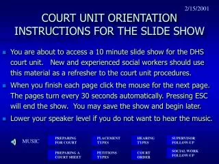
INSTRUCTIONS SLIDE Welcome 1 This is a template to create an Instructional Design Document of the concept you have selected for creating animation. This will take you through a 5 section process to provide the necessary details to the animator before starting the animation. The legend on the left will indicate the current status of the document. The Black coloured number will denote the current section, the Turquoise color would denote the completed sections, and the Sky blue color would denote the remaining sections. The slides having 'Instructions' would have a Yellow box, as shown on the top of this slide. 2 3 4 5
Write the Title of the concept here Your Name: Chaitanya Tiwari Department : Mechanical Engineering Roll no:08310911 E-Mail :08310911@iitb.ac.in Add Course Instructor/Instructors name here: Prof. M. S. C. Bose
Definitions and Keywords 1 • Add the keywords with definitions which are used in this concept • Add more slides if required 2 3 4 5
GEAR:- A gear is a component within a transmission device that transmits rotational torque by applying a force to the teeth of another gear or device.
Gear (bigger) Pinion (smaller) Figure 1
Pitch Cylinder:- Pitch cylinders of a pair of gears in mesh are the imaginary friction cylinders, which by pure rolling together, transmit the same motion as the pair of gears.
PitchCylinders Figure 2
Pitch Circle:- It is a circle corresponding to a circle of equivalent pitch cylinder by a plane normal to the wheel axis. The point of intersection of two circles is known as the pitch point.
Pitch Circle Figure 3
Pitch Circles Pitch Point Figure 4
Addendum Circle:- It is the circle passing through the tips of the teeth. The Radial height of a tooth above the pitch circle is known as addendum.
AddendumCircle Pitch circles Figure 5
Dedendum or Root Circle:- It is a circle passing through the roots of the teeth. The radial height of a tooth below the pitch circle is known as dedendum.
Addendum Circle DedendumCircle Figure 6
Base circle:- Applies only to involute gears, where the tooth profile is the involute of the base circle. The radius of the base circle is somewhat smaller than that of the pitch circle.
BaseCircle (Red circle) Figure 7
AddendumCircle DedendumCircle PitchCircle BaseCircle Figure 8
Full Depth of teeth:- It is the total radial depth of the tooth space. Full depth = Addendum + Dedendum Working depth :- Sum of addendums of the two gears.
Total Working depth full depth of teeth (Radialy) Figure 9
Full Depth of teeth Figure 10
Space width :- It is the width of the tooth space along the pitch circle. Tooth thickness:- It is the thickness of the tooth measured along the pitch circle. Back lash:- It is the difference between the space width and the tooth thickness along the pitch circle. Face width:- The length of the parallel to the gear axis is the face width.
Top land :- It is the surface of the top of the tooth. Bottom land :- the surface of the bottom of the tooth between the adjacent fillets. Face :- tooth surface between the pitch circle and the top land. Flank :- Tooth surface between the pitch circle and the bottom land including fillet. Fillet :- It is the curved portion of the tooth flank at the root circle.
INSTRUCTIONS SLIDE Concept details: 1 • In this section, provide the stepwise detailed explanation of the concept. • Please fill in the steps of the explanation of the concepts in the table format available in the slides to follow (see the sample below). • Resize the table dimensions as per your requirements. 2 3 4 5
Concept details 1 2 Rotating motion of the two cylinder similar to gear 1 Pitch cylinders Figure 2 Slide 6 3 Clearly show two pitch circles on two rotating Pitch cylinder Slide 8 2 Pitch circle Figure 3 & 4 4 Clearly show two Addendum circles on two rotating Pitch cylinder 3 Addendum circle Figure 5 Slide 11 5
Concept details 1 2 Clearly show two dedendum circles on two rotating Pitch cylinder 4 Dedendum circle Figure 6 Slide 13 3 Clearly show two base circles on two rotating Pitch cylinder Base circle Figure 7&8 Slide 15 5 4 Clearly show all circles on two rotating Pitch cylinder 6 All circles Figure 8&9 Slide 17 5
Concept details 1 2 Generate Gear tooth from the circles and show transfer of rotary motion 7 Gear tooth Figure 9 Slide 19 3 Show as per the diagram Full depth and working depth Slide 18 8 Figure 9&10 4 Clicking on each attribute will show corresponding area on gear tooth as shown in diagram Definitions Figure 11 As per Slide 21&22 9 5
INSTRUCTIONS SLIDE 1 Interactivityand Boundary limits expected in the animation • In this section provide, interactivity options for all the parameters/components of the concept. • For example: • Numerical values to change the state of the component: By providing input boxes • Drag and drop of components: To test the comprehension of the users • Movement of objects: To explain the action of the components • Provide the boundary limits of the parameters, which will enable correctness of the results of the experiment. 2 3 4 5 gas
Interactivityand Boundary limits 1 2 After creating complete Gear and showing motion, bullets representing headings shown in the slides 21 & 22 should appear and clicking on each should show the corresponding figures on the gear. Corresponding definition as per Slide 21&22 Figure 11 3 4 5
INSTRUCTIONS SLIDE 1 Questionnaire to test the user • A small, (5 questions) questionnaire can be created in the next slide, to test the user's comprehension. • This can be an objective/subjective type questionnaire. • It can also be an exercise, based on the concept taught in this animation. 2 3 4 5
Questionnaire[ modify as per your requirement] 1 1. Answers: a) b) c) d) 2. Answers: a) b) c) d) 3. Answers: a) b) c) d) 4. Answers: a) b) c) d) 5. Answers: a) b) c) d) 2 3 4 5
(1) Pinion is used as _______ gear. Driving (2) Define gear ratio? It is the ratio of no. of teeth on the gear to that on the pinion. (3) What are the materials used for gears? Steel (Medium carbon steel), Cast iron, Bronze, Phenolic resins
(4) Write important critical material parameters that must be consider for making gears? Allowable bending and hertz stress Wear resistance Impact strength (5) Write importance of base circle? Above it involute profile starts.
INSTRUCTIONS SLIDE Links for further reading 1 • In the subsequent slide, you can provide links, which can be relevant for the user to understand the concept further. • Add more slides in necessary 2 3 4 5
Links for further reading 1 . (1) Design of machine elements by V. B. Bhandary (2)Theory of machine by S S Ratan (3) http://en.wikipedia.org/wiki/Gear 2 3 4 5


![Instructions [please delete this slide before submitting]](https://cdn2.slideserve.com/3605613/instructions-please-delete-this-slide-before-submitting-dt.jpg)