Design Comparison
Design Comparison. Selection of OMT Design for the EVLA X-band Receiver. Bob Hayward Senior Engineer. What’s Next…. We have 4 possible OMT designs to chose from… These need to be evaluated & compared with the following in mind: Performance Cost Schedule Impact

Design Comparison
E N D
Presentation Transcript
Design Comparison Selection of OMT Design for the EVLA X-band Receiver • Bob Hayward • Senior Engineer
What’s Next… • We have 4 possible OMT designs to chose from… • These need to be evaluated & compared with the following in mind: • Performance • Cost • Schedule Impact • Any outstanding technical Issues • These aspects also have to be properly weighted • If you have 2 receiver designs and one is twice as sensitive as the other but costs twice as much and takes twice as long, is it still worth it? • This is why the EVLA Program Manager gets paid the Big Buck$…
EVLA X-Band OMT Specifications • Performance Specifications (based on higher frequency Wollack OMT designs): • Return Loss < -15 dB (required) • < -20 dB (desired) • Insertion Loss < -0.2 dB • Isolation < -35 dB • Obviously any OMT that exceeds these specs gets brownie points
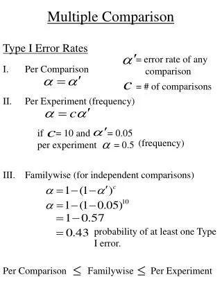
VLA/EVLA(29 July 2009)TRx versus Frequency Simple Noise Model : TRx = m·F + b ; m = 0.5°K/GHz ; b = 8°K
Waveguide OMT Comparison • Turnstile & Offset Quadridge designs give better RF performance than a Planar OMT but at the cost of a large Dewar package • Length of Waveguide Circular Polarizers: • Turnstile OMT based Polarizer Length: • Circular to square transition = 2.3" • Phase Shifter = 8.1" • 45° Twist = 3.5” • OMT = 2.7” • Dimensions of RF tree L x W = 16.6“ x 9.3” • Quadridge OMT based Polarizer Length: • Circular to square transition = 2.3" • Phase Shifter = 8.1“ • OMT = 6.1” • Dimensions of RF tree L x W = 16.5“ x 2.0” • Both designs too big to fit inside the existing VLA X-Band Dewar, which was the design constraint leading to the Planar OMT development effort
Turnstile vs. Offset Quadridge • Both OMTs have very similar Return Loss and Isolation performance • Turnstile OMT has slightly better Insertion Loss (0.15 vs 0.30 dB) because it is inherently a waveguide device • This might allow for the option of maintaining a lower loss waveguide path all the way up to and including the LNA input • Similar to the design of the EVLA Ku-Band receiver which uses a Srikanth Phase-Shifter + Wollack OMT • Requires using a waveguide cross-guide coupler (custom/commercial) • Requires a cryogenic junction isolator (0.2 dB lower loss than Coaxial Iso) • CDL will have to modify their 8-12 GHz LNAs so that a WR90 flange replaces the K-Connector input – Marian might enjoy the challenge! • The Turnstile OMT layout needs a slight redesign so that the waveguide outputs come out the top of the block rather than the bottom so the CC+Iso+LNA assemblies sit in the “dead space” around the Phase-Shifter • Offset Quadridge has equivalent performance to the Turnstile if the latter has WR90-to-Coax adapters installed to provide SMA outputs
Planar OMT Development • Work package for the design of an X-Band Planar OMT has been underway by Stennis for less than a year • The effort to develop the successful EVLA Quadridge OMTs for L/S/C-Band took over 6 years and 4 different engineers (Lilie, Locke, Stennis and Coutts) • Stennis had to investigate numerous design avenues & novel planar techniques for two OMT designs (Normal vs. Superconducting) • Design of dual thermal gap assemblies (300/50K & 50/15K) • Planar waveguide probes • Microstrip 180°and 90°Hybrids Couplers & 30 dB Directional Couplers • Gold on Alumina microstrip circuits • High Temperature (HTS) microstrip circuits • Modified old X-Band Dewar to perform full-up cryogenic system tests • The current development phase is incomplete & should continue no matter what the X-OMT decision turns out to be as this design might eventually have a useful role to play (maybe a 3:1 BW for SKA)
Planar OMT Return LossWG Probe & 180/90°Couplers Not Yet Optimized
Planar OMT Insertion LossProblems with 50/15K Thermal Gap & Interconnects
Planar OMT IsolationProblems with Microstrip Cross-overs and 90°Hybrids
TRX Noise Model Estimates • To compare the noise performance of the various OMTs, a noise model is used to estimate the Receiver Temperature based on • Insertion Loss measured for each OMT • Insertion Loss of the various other components (e.g., Phase-Shifter, Cal Coupler, Cryogenic Isolator, etc.) • Physical Temperature of all these components • Depending on the OMT, some components in the model are not needed and are excised from the noise calculations • An attempt is also made to predict the effect of cooling with Model 350 & Model 22 refrigerators • No attempt is made to model reflections (i.e., Return Loss of the various components in the signal path) or changes in the IL as the component gets colder • No attempt to predict the change in LNA noise temperature with slight changes in physical temperature • Some of the estimated values may be incorrect but they will be equally wrong for all the OMT scenarios
Receiver Temperature EstimatesBest Case “Baseline” Scenario with Model 350
Receiver Temperature EstimatesTurnstile OMT Waveguide Scenario with Model 350
Receiver Temperature EstimatesTurnstile OMT Coaxial Scenario with Model 350
Receiver Temperature EstimatesTurnstile OMT Waveguide Scenario with Model 22
Receiver Temperature EstimatesTurnstile OMT Coaxial Scenario with Model 22
Receiver Temperature EstimatesOffset Quadridge OMT Coaxial Scenario with Model 350
Receiver Temperature EstimatesOffset Quadridge OMT Coaxial Scenario with Model 22
Receiver Temperature EstimatesHTS Planar OMT Scenario with Model 350
Receiver Temperature EstimatesHTS Planar OMT Scenario with Model 22
Receiver Temperature EstimatesGold/Alumina Planar OMT Scenario with Model 350
Receiver Temperature EstimatesGold/Alumina Planar OMT Scenario with Model 22
What about a “Hot” Polarizer ? • For the Turnstile & Quadridge OMTs, if a Model 22 fridge is unable to cool the entire Circular Polarizer and as a result we also end up with all the components mounted on the 15K plate running warm, one option is to only cool the Circ-Sq + PS + OMT to 50K and have the CC + Iso + LNA properly chilled on the 15K stage • This is similar to an EVLA L or S-Band receiver where the OMT is tied to the 50K stage • This option is explored in the following noise models…
Receiver Temperature EstimatesTurnstile OMT Scenario cooled to 50K (Model 22 )
Receiver Temperature EstimatesQuadridge OMT Scenario cooled to 50 K (Model 22)
TRx SummaryBest, 2nd Best, 3rd Worst, Worst • Lowest noise solution is the Turnstile with a Model 350 fridge (10.9K ) • Best Model 22 solution (assuming a 350 is required to adequately cool a Turnstile) is the Quadridge OMT (14.2K) • Best Planar OMT is the HTS solution (15.9K, assuming IL, RL & Iso problems resolved )
Cost ComparisonBest=1, 2, 3, 4=Worst • The Planar OMT is the least difficult to machine. The Turnstile OMT is the most difficult due to the amount of precision facing required. • Assembly cost of the Turnstile is the least. The Quadridge requires fine tuning of the coaxial probes. The Planar OMT assembly is much more extensive due to mounting of microstrip carriers and wire bonding. • Cost of materials, components and machining is the least for the Quadridge and the highest for the HTS Planar OMT. • Dewar costs are the least for the Planar OMT (reuses old X-Band Dewar) & highest for the Turnstile, especially if new Model 350 used. • If Turnstile OMT requires a 350, a costly cascade occurs because of the need for a 4th Compressor (but could improve L-Band operations).
X-Band Deployment Schedule • The production of new EVLA X-Band receivers is slated to begin in early 2010. • To ensure that all new X-Band receivers are installed on the EVLA by the end of 2012, it will require fielding about 1 receiver per month through the end of the Project • Any delay at the start will likely delay the completion since it will compete with manpower resources for the fabrication and testing of the new L, S, Ku-Band receivers • While the machining man-hours is the least for Planar OMT (since it would reuse about 75% of the old VLA Dewar), it requires the most assembly effort from the FE Group (complicated mounting of sub-strates, wire bonding and testing/rework) • While the Turnstile OMT requires a brand-new wider-diameter Dewar, it has recently been determined that the Quadridge OMT can reuse very little of the old VLA Dewar so both OMTs have similar manpower machining and assembly requirements • Design of Dewar for Quadridge OMT is further along than that for a Turnstile OMT so this effort would have to be accelerated if it was chosen for the new design
Turnstile OMT Evaluation • Pros: • Polarizer option with the highest sensitivity • OMT design is essentially complete (should be modified for output waveguide to come out the top) • Allows signal path in low-loss waveguide right up to LNA input • Polarization purity should be excellent (depends on amplitude and phase balance of Phase-Shifter) • Cons: • Circulator polarizer is fat and long – requires a brand new Dewar design • Likely requires a Model 350 refrigerator for best cooling • If so, requires a 4th Compressor (would help L-Band cooling) • Requires CDL to modify 8-12 GHz LNA for waveguide input flange • Machining & assembly cost is slightly higher than the Quadridge OMT
Offset Quadridge OMT Evaluation • Pros: • Provides 2nd best polarizer sensitivity option • OMT design is essentially complete • Coolable with a Model 22 fridge • Polarization purity should be excellent (depends on amplitude and phase balance of Phase-Shifter) • Machining cost is slightly less than the Turnstile OMT • Small 2”x2” cross-section would make it perfect for a prime-focus focal plane array • Cons: • Slightly higher Insertion Loss than the Turnstile OMT and no option to use lower-loss waveguide signal path up to LNA input • Circulator polarizer is long and narrow – requires a brand new Dewar design (reuse of any of the VLA X-Band Dewar is unlikely) • Model 22 cooling is close to the margin – Helium supply pressure is critical
Au/Alumina Planar OMT Evaluation • Pros: • Easily fits within the old VLA Dewar • Coolable with a Model 22 fridge • Integrated the Hybrid and Cal Couplers in a single block • Lowest cost for machining both the OMT and Receiver package • Lower Insertion loss might come from further optimization (perhaps half that of prototype) • Cons: • Highest Insertion Loss and thus the least sensitive option (more development would likely cut the loss in half) • Cost of assembly is higher than the other OMTs • Polarization purity yet to be investigated (may require tuning of the amplitude and phase at the input to the 90°Hybrid) • More development effort required to optimize performance (less than a year to date so far to investigate this truly novel technique)
HTS Planar OMT Evaluation • Pros: • Ditto as for Au/Alumina version • Lower Insertion loss might come from further optimization, possibly competitive with the Quadridge OMT (perhaps as low as 0.6 dB) • Cons: • Ditto as for Au/Alumina version • Robustness to moisture could be a serious problem (HTS circuits must be passified somehow) • More development effort required to optimize design
Recommendations • If money was no option, the Turnstile OMT would provide the lowest noise receiver but… • We will need to design a new Dewar and receiver package • Assumes we can keep the signal in waveguide right up to the LNAs • Plus add a 4th Compressor (but this will allow opportunities to improve the cooling of L-Band receivers as well as increase compressor reliability) • The Quadridge OMT is probably the best Model 22 option we have • Especially if the Turnstile all-waveguide OMT could not be cooled as low as the Quadridge without a Model 350 • Will need to design a new Dewar & receiver package (largely complete) • The HTS Planar OMT is an attractive option but if the decision had to be made today, it still has a number of concerns that need to be more fully addressed, such as… • Can the Insertion Loss, Input Return Loss and Cross-Pol/Isolation be improved and be made repeatable? • How do we tune the amplitude & phase match of the 90° Hybrid for good circular polarization Axial Ratio performance? • Will the HTS microstrip circuits be robust enough?
So it all depends on how much money the EVLA Program Manager has in his Contingency Fund and how low-noise a receiver the astronomers want in the 8-12 GHz band…