Wireless Power Prototype for Household Devices: A Solution to Reduce Wire Clutter
Explore the innovative concept of wirelessly powering household appliances through a prototype device. This project aims to test wireless power delivery, reduce wire clutter, and enhance convenience for users. With a detailed engineering report, schematics, and part list provided, this project offers a step-by-step guide on creating a wireless power system using readily available materials. The focus is on improving power transfer efficiency and applying the concept to larger areas for potential future applications. Witness the successful transfer of power between wire coils and delve into the possibilities of wirelessly charging devices. Join the movement towards a wire-free future with this cutting-edge project! (

Wireless Power Prototype for Household Devices: A Solution to Reduce Wire Clutter
E N D
Presentation Transcript
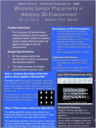
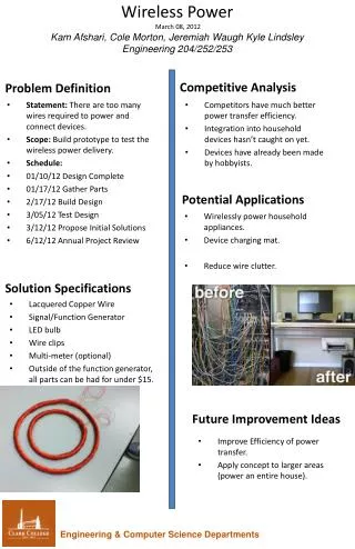
Wireless Power March 08, 2012 KamAfshari, Cole Morton, Jeremiah Waugh Kyle LindsleyEngineering 204/252/253 • Competitors have much better power transfer efficiency. • Integration into household devices hasn’t caught on yet. • Devices have already been made by hobbyists. Problem Definition Competitive Analysis Wirelessly power household appliances. Device charging mat. Reduce wire clutter. • Statement: There are too many wires required to power and connect devices. • Scope: Build prototype to test the wireless power delivery. • Schedule: • 01/10/12 Design Complete • 01/17/12 Gather Parts • 2/17/12 Build Design • 3/05/12 Test Design • 3/12/12 Propose Initial Solutions • 6/12/12 Annual Project Review Potential Applications Solution Specifications • Lacquered Copper Wire • Signal/Function Generator • LED bulb • Wire clips • Multi-meter (optional) • Outside of the function generator, all parts can be had for under $15. Future Improvement Ideas • Improve Efficiency of power transfer. • Apply concept to larger areas (power an entire house). Engineering & Computer Science Departments
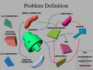
Report: • Creation Process: • 1: Get the required wire, in our case we used copper wire insulated by a lacquer coating. • 2: Wind wire into a loop. It is recommended that you count the number of loops created as well as keeping the wires as tightly wound as possible. • 3: Repeat step two to create a second wire coil. Make a good effort to keep the two coils very similar in size (circumference of the loops) without being exactly the same. This is to create more reliable and efficient power transfer. • 4: Run an AC current through one of the wire coils. Use a function generator and make sure to use a square wave function as well. A multi-meter here would be helpful in determining the voltage being supplied. With a voltage reading, you can then determine the frequency that will generate the most voltage for your particular wire coil. • 5: Place the second wire coil inside (or around depending on the sizes) the first coil. Attach a load to this second coil and view the results. A second multi-meter would be beneficial as well to read the voltage being received. • 6: Once step five is complete, you should have a working device that transfers power between two points wirelessly. Feel free to play around and see how the voltage transfers change based on the location of the two rings. • Schematic: • A and B represent the coils of wire. A function generator sends AC voltage through coil A, and then using the wireless power transfer of the resulting magnetic field, coil B receives power. The power coil B receives is then sent on to the load (Vo). In our trials we used a basic LED. • The amount of power transferred depends on a number of things, including the number of loops in each coil of wire. The distance the wires are apart from each other also helps determine the power of the magnetic field. • Part List: • Lacquered Copper Wire • Signal/Function Generator • LED bulb (or similar load) • Wire Clips • Multi-meter (optional but recommended) • Results: • Our group was able to effectively transfer power between the two wire coils. The transfer rate was approximately 30-50% of the original voltage depending on the function generator. While this is an inefficient model in that regard, it is good enough to light the LED and show the concepts at work. Future goals or improvements will definitely be centered around improving the efficiency rates of the power transfer.