Download
1 / 16
160 likes | 292 Vues
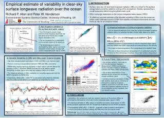
Advances in Measurement of Shortwave and Longwave Radiation at Sea. Chris Fairall Weather and Climate Physics Branch Physical Sciences Division NOAA/ESRL Boulder, Colorado E.F. Bradley CSIRO Canberra, AU R.A. Weller WHOI, USA R. Lukas University Hawaii, USA

E N D
Advances in Measurement of Shortwave and Longwave Radiation at Sea Chris Fairall Weather and Climate Physics BranchPhysical Sciences DivisionNOAA/ESRLBoulder, Colorado E.F. Bradley CSIRO Canberra, AU R.A. Weller WHOI, USA R. Lukas University Hawaii, USA Diane Stanitski NOAA Clim.Obs. Div, USA
BIG PICTUREOceanic Near-Surface Flux Observations:A Major EffortGulev et al., Surface energy and CO2 fluxes in the global ocean-atmosphere-ice system. Plenary White Paper, OceanObs2009 • Satellite • J-Ofuro, HOAPS, IFREMER, Goddard • Blended/Hybrid • OAFlux (WHOI), CORE (NCAR), U. Wash. • In situ • SAMOS Archive of R/V (20 vessels) • Ocean Sites Archive flux buoys (20 sites) • Operational TAO/PIRATA/RAMA (200 sites) • VOSCLIM Volunteer vessels with special sensor package Accuracy Requirement? There isn’t one - i.e, there are many. In situ Obs Target – 1 week time scale, residual bias no larger than ±5 W/m^2 IR or Solar Irradiance; Improvement to ±1 W/m^2 very useful
Simple Thermopile-Driven Heat Balance Radiative Flux Sensors Solar Flux – Pyranometer Flux = 0 to 1200 W/m^2 Calibration determines Asol 2nd order: cold sky bias Non-cosine response IR Flux – Pyrgeometer Flux = 200 to 450 W/m^2 Calibration determines AIR and B First term = -100 to 0 Second term = 200 to 450 Third term = -50 to +10 Tcase = case temperature Tdome = dome temperature 2 C difference gives 50 W/m^2
Calibration Methods 1*Factory calibrations 1-2 year Eppley Kipp & Zonen 2*Use special calibration facilities NOAA/GMD Boulder Lab DOE ARM Oklahoma 3*Keep your own secondary standard (see 1 & 2) 4*Field intercomparisons with an ensemble of sensors A Few Ensemble Intercomparisons *Post COARE, Fairall et al. JTECH 1998 *Arctic (SHEBA) Persson et al. JGR 2002 *Comprehensive land-based: Philipona et al, ‘Atmospheric longwave irradiance uncertainty: Pyrgeometers compared to an absolute sky-scanning radiometer, atmospheric emitted radiance interferometer, and radiative transfer model calculations’, JGR 2001 Rooftop radiative flux sensor calibration facility NOAA/ESRL/GMD Boulder, CO
TOGA COARE (1992-1993)Tropical Western Pacific *Set target accuracy *Field intercomparisons Ship, Aircraft, Buoy *Post experiment calibrations Weller, R., F. Bradley, and R. Lukas, 2004: The interface or air-sea flux component of the TOGA Coupled Ocean-Atmosphere Response Experiment and its impact on subsequent air-sea interaction studies. J. Atmos. Oceanic Tech., 21, 223-257. Time series of surface flux component accuracies from 1970’s to today (Colbo and Weller, 2009)
TOGA COARE Surface Sensor Calibration Adjustments Weller et al. 2004 Solar: Sensitivity Coefficient Adjustment (rms 3%) IR: Bias Adjustment (rms 10 W/m^2); Dome Heating Corrections
Joint NOAA/PSD-WHOI Flux Accuracy and Quality Assurance Project for Research Vessels and Flux Reference Buoys
Solar and IR Comparison Stratus 200415 Radiometers on the Ship Main Result – Voltage amplifier issues with one model of Buoy radiometers
Solar Comparison Stratus 20076 solar and 3 IR Radiometers on the Ship • By 2007 have concluded IR fluxes accurate to 3-5 W/m^2 • Solar difficult to compare during cloudy periods • Eppley pyranometers (PSD and WHOI) about 4% lower than K&Z Red – clear sky model; Blue – K&Z; Green - Eppley
Further Analysis of Stratus 2007 Solar DataEppley and K&Z relative calibration Ratio of K&Z to Clear sky and Ratio of Eppley to Clear sky during clear periods Ratio of Eppley to K&Z vs Zenith Angle
Results of the Boulder and Eppley Solar Calibrations • Both PSD Eppleys used on Stratus2007 and WHOI Standard Eppley had lost about 4% sensitivity due to aging • Boulder NOAA/GMD rooftop and K&Z rooftop calibrations are very close. Eppley (laboratory light hemisphere) about 1% lower (possible cold bias effect?) • Conclusion: Modern factory calibrations unbiased to about 1% (3-4 W/m^2) but need to be done yearly. • Measurements to greater accuracy will likely require different technology (sun tracking)
Confirmation from Hawaii Deployment Upper Left: Radiometer comparisons during daylight hours on Days 193 to 194 (I/C day 2). The lower left panel shows an expanded period around local noon.
General Guidelines *Yearly calibrations *Ensemble comparisons useful *Ventilation and/or quartz domes helps *Microvolt accuracy on data logger *Pyranometer – calibration coefficient is critical *Pyrgeometer – dome/case temperature calibration is critical (0.1 C = 3 W/m^2) *Pitch/roll leveling - ???? NUTS and BOLTS STUFF: Bradley, F. & Fairall, C., (2007). A Guide to Making Climate Quality Meteorological and Flux Measurements at Sea. NOAA Technical Memorandum OAR PSD-311, NOAA/ESRL/PSD, Boulder, CO, 108.
Selected References • Bradley, E.F. and C.W. Fairall, 2007: A Guide to Making Climate Quality Meteorological and Flux Measurements at Sea. NOAA Technical Memorandum OAR PSD-311, NOAA/ESRL/PSD, Boulder, CO, 108 pp. • Burns, Sean P. and 14 coauthors, 2000: Comparisons of aircraft, ship, and buoy radiation and SST measurements from TOGA COARE. J. Geophys. Res., 105, 15627-15652. • Colbo, K. and R.A. Weller, 2009: Accuracyof the IMET sensor package in the subtropics. J. Atmos. Oceanic Tech., 26, 1867–1890. • Cronin, M., C. W. Fairall, and M. J. McPhaden, 2006: An assessment of buoy-derived and numerical weather prediction surface heat fluxes in the tropical Pacific. J. Geophys. Res., 111, C06038, doi:10.1029/2005JC003324. • Fairall, C. W., O.P.G. Persson, R. E. Payne, and E. F. Bradley, 1998: A new look at calibration and use of Eppley precision infrared radiometers. J. Atmos. Oceanic Tech., 15, 1230-1243. • Fairall, C.W. and 17 coauthors, 2009: Observations to Quantify Air-Sea Fluxes and Their Role in Climate Variability and Predictability. Community White Paper, OceanObs09, Venice, Italy. [http://www.oceanobs09.net/blog/?p=73 ] • Persson, P. O. G., C. W. Fairall, E. L. Andreas, P. Guest, and D. Perovich, 2002: Measurements near the Atmospheric Surface Flux Group tower at SHEBA : Near surface conditions and surface energy budget. J. Geophys. Res., 107, NO. C10, 8045, doi:10.1029/2000JC000705, 2002. • Philipona et al, 2001: Atmospheric longwave irradiance uncertainty: Pyrgeometers compared to an absolute sky-scanning radiometer, atmospheric emitted radiance interferometer, and radiative transfer model calculations. J. Geophys. Res., 106, 28,129-28,141. • Weller, R.A., E.F. Bradley, and R. Lukas, 2004: The interface or air-sea flux component of the TOGA Coupled Ocean-Atmosphere Response Experiment and its impact on subsequent air-sea interaction studies. J. Atmos. Oceanic Tech., 21, 223-257. • Weller, R. A., E. F. Bradley, J. B. Edson, C. W. Fairall, I. Brooks, M. J. Yelland and R. W. Pascal, 2008: Sensors for physical fluxes at the sea surface: energy, heat, water, salt. Ocean Science, 4, 247-263.