Download

1 / 129
1.3k likes | 1.33k Vues
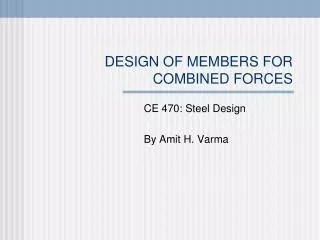
This module covers the analysis and design of steel structural members subjected to combined axial load, bending, and shear forces. It addresses second-order effects, direct analysis methods, and considerations for multiple stress states.

E N D
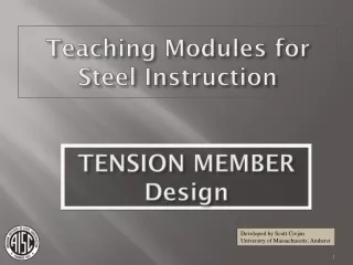
Teaching Modules for Steel Instruction Combined Load Member Design Developed by Scott Civjan University of Massachusetts, Amherst
COMBINED FORCES: Structural member subjected to axial load, bending and shear Va Vb Pb Pa Ma Mb Combined Forces Module
Combined Forces: • Chapter H: Combined Forces • Chapter C: Direct Analysis Method • Chapter C: Other Analysis Requirements • Appendix 7: Alternative Analysis Methods • Appendix 8: Approximate 2nd Order Analysis • Chapter B: Local Buckling Classification • Part 6: Design Tables Combined Forces – AISC Manual 14th Ed
COMBINED FORCES: Combinations of flexural and axial forces need to be addressed in both analysis and design. Analysis needs to consider second order effects (analysis based on final deformations). Design needs to consider combinations of forces in a member. Combined Forces Module
COMBINED FORCES: Major Issues to Address: Combination of multiple states of stress. Second order load effects. Direct analysis versus traditional K methods. Combined Forces Theory
Combination of multiple states of stress: Bending about the major and minor axis will combine to provide maximum stresses in the corner of a W shape. s3=P/A s1=Mxcy/Ix Axial load will provide uniform stresses across the member and add to other maximum stresses. s2=Mycx/Iy (elastic range) Combined Forces Theory
Combination of multiple states of stress Bending in each direction occurs simultaneously with associated shear stresses. For elastic analysis one can superimpose stresses and arrive at a maximum value. Actual design may include inelastic behavior and needs to account for residual stresses. Once behavior becomes inelastic the resulting stresses are very difficult to calculate. Combined Forces Theory
Combination of multiple states of stress Design provisions are simplified and rely on the inherent ductility of steel to redistribute stresses throughout the section. The basic principle for design is an interaction equation which combines axial and bending forces with shear being checked independently. Modes of failure from all independent modes are analyzed independently of other modes and forces. This does not capture complete behavior, but is sufficiently accurate for design purposes. Combined Forces Theory
DIRECT ANALYSIS OR “TRADITIONAL” METHODS Analysis methods and design calculations are determined by the method used. Direct Analysis applies additional “notional” loads and reduced member stiffness but uses K = 1 in column design. Traditional method uses calculated K values (alignment chart) in column design and nominal stiffness properties. Combined Forces Module
Combined Forces Analysis and Design Direct Analysis Method (C1.1) or traditional methods (Appendix 7) may be used, but analysis and design must be consistent with the single approach chosen. Interaction Equations of Chapter H are applied for member design acceptance. Values used in these equations must be consistent with the analysis and design method used. Combined Forces – AISC Manual 14th Ed
Doubly and Singly Symmetric Members: • Flexure and Compression Combined Forces – AISC Manual 14th Ed
Combination of multiple states of stress: Design provisions are simplified and rely on the inherent ductility of steel to redistribute forces throughout the section. The basic principle for design is an interaction equation which combines forces from axial and bending loads. Shear is checked independently. Modes of failure from all independent modes are analyzed independently of other modes and forces. This is not completely realistic, but is sufficiently accurate for design purposes. Combined Forces – AISC Manual 14th Ed
Doubly and Singly Symmetric Members: Flexure and Compression Equation H1-1a For For Equation H1-1b Combined Forces – AISC Manual 14th Ed
Doubly and Singly Symmetric Members: Flexure and Compression Pr = required axial compressive strength from 2nd ORDER ANALYSIS (from LRFD load combinations). Pc = available design axial compressive strength LRFD (strength from Chapter E). Mr = required flexural strength from 2nd ORDER ANALYSIS (from LRFD load combinations). Mc = available design flexural strength LRFD (strength from Chapter F). x = strong axis bending y = weak axis bending Combined Forces – AISC Manual 14th Ed
fcPn Axial Load Pu 0.2fcPn 0.9fbMn fbMn Uniaxial Flexural Load, Mu For uniaxial bending the interaction equations are depicted above (LRFD). Pure axial or flexural load results in strength identical to Chapters E and F. Combined Forces – AISC Manual 14th Ed
Doubly and Singly Symmetric Members: • Flexure and Tension Combined Forces – AISC Manual 14th Ed
Doubly and Singly Symmetric Members: Flexure and Tension The same equations are used for tension and compression. (H1-1a and H1-1b) Substitute: Pr = required axial tensile strength (from LRFD load combinations) Pc = available design axial tensile strength LRFD (strength from Chapter D) Additionally, for Mc Cb can be increased per Section H1.2. Lateral torsional buckling design strength increases due to tension. Combined Forces – AISC Manual 14th Ed
Analysis Requirements of AISC Combined Forces – AISC Manual 14th Ed
Combined Forces Analysis and Design Second order analysis is required per C1. Any rational method that accounts for both P-D and P-d is acceptable. Second order analysis for LRFD uses load combinations. Combined Forces – AISC Manual 14th Ed
Combined Forces Analysis and Design Typically computer analysis is used to calculate second order effects. Many programs neglect P-d analysis. Often not a significant effect, but this should be checked. P-d analysis can be neglected if requirements of Section C2.1(2) are met. Combined Forces – AISC Manual 14th Ed
Combined Forces Analysis and Design Initial imperfections must be considered, either through application of notional loads or direct modeling. Notional loads are applied to all load cases (Section C2.2b(1)) unless second order to first order drift ratio is ≤ 1.7. Then can apply notional loads only to gravity load combinations (Section C2-2b(4)). This last provision is applicable to the “traditional” method restrictions, therefore often requires the application of notional loads in fewer cases than the direct analysis method. Combined Forces – AISC Manual 14th Ed
Combined Forces Application of notional loads (Section C2-2b). Ni = 0.002Yi Ni = notional lateral load applied at level i Yi = gravity load at level i from load combinations Consider independently in two orthogonal directions. Combined Forces – AISC Manual 14th Ed
Chapter C: Direct Analysis Method Combined Forces – AISC Manual 14th Ed
Direct Analysis Method Analysis REQUIRED if D2nd Order/D1st Order > 1.5 (B2 > 1.5) (Section Appendix 7.2.1) K = 1 for all design Second order analysis (P-d and P-D) required, such as verified computer analysis or amplified first order analysis. Combined Forces – AISC Manual 14th Ed
Direct Analysis Method Reduce Stiffness EI* and EA* per Section C2.3: Stiffness adjustments are applied to all components that contribute to the stability of the structure (Section C2.3) Stability is typically affected by flexural stiffness of members in moment frames and axial stiffness of braced frame components. Combined Forces – AISC Manual 14th Ed
Direct Analysis Method Reduce Stiffness EI* per Section C2.3: EI* = 0.8tbEI. E = modulus of elasticity I = moment of inertia about axis of bending tb= reduction factor for inelastic action Required for all members that contribute to lateral stability of the structure (safe to include for all members). Combined Forces – AISC Manual 14th Ed
Direct Analysis Method Reduce Stiffness EI* per Section C2.3: tb = Reduction Factor for Inelastic Action for for Equations C2-2a and C2-2b Pr= required axial compressive strength Py=FyA = member yield strength a = 1.0 (LRFD), 1.6 (ASD) Combined Forces – AISC Manual 14th Ed
Direct Analysis Method Reduce Stiffness EI* per Section C2.3: If an additional notional load of Ni = 0.001aYi is applied at all levels in all load combinations (even if Section C2.2b(4) applies), tb = 1 per Section C2.3(3) Therefore, all stiffness could be adjusted similarly Combined Forces – AISC Manual 14th Ed
Direct Analysis Method Reduce Stiffness EA* per Section C2.3: EA* = 0.8EA E = modulus of elasticity A = cross sectional member area Required for all members that contribute to lateral stability of the structure (safe to include for all members). Combined Forces – AISC Manual 14th Ed
Chapter B: Local Buckling Criteria Combined Forces – AISC Manual 14th Ed
Local Buckling Criteria Defined in Table B4.1 Since members are analyzed independently under flexural and axial loads, the local buckling provisions are checked separately for use in calculations related to each member type. This does not directly address the combination of stresses which may make web local buckling less likely to occur for some load conditions. Combined Forces – AISC Manual 14th Ed
2nd Order Effects Theory Combined Forces – AISC Manual 14th Ed
Second Order Effects Equilibrium is based on DEFORMED GEOMETRY. Initially, consider a member subjected to flexure only. Combined Forces Theory
Second Order Effects Equilibrium is based on DEFORMED GEOMETRY. Initially, consider a member subjected to flexure only. Application of load results in mid-span deflection d0, from basic derivations. d0 Combined Forces Theory
Second Order Effects Equilibrium is based on DEFORMED GEOMETRY. Now consider the same member with Axial load P. P P Combined Forces Theory
Second Order Effects Equilibrium is based on DEFORMED GEOMETRY. Axial force acting through deformations results in additional moment P(d0) at center of span. d0 Combined Forces Theory
Second Order Effects Equilibrium is based on DEFORMED GEOMETRY. Axial force acting through deformations results in additional moment P(d0) at center span. Additional moment then results in displacement d’. d’ d0 P P Combined Forces Theory 37
Second Order Effects Equilibrium is based on DEFORMED GEOMETRY. Axial force acting through deformations results in additional moment P(d0) at center span. Additional moment then results in displacement d’. Resulting in additional moment P(d’) d’ d0 P P Combined Forces Theory 38
Second Order Effects Equilibrium is based on DEFORMED GEOMETRY. Axial force acting through deformations results in additional moment P(d0) at center span. Additional moment then results in displacement d’. Resulting in additional moment P(d’) d’ d0 P P Combined Forces Theory 39
Second Order Effects Equilibrium is based on DEFORMED GEOMETRY. This either results in an incremental failure, or stabilizes. d > d0 and M > M0 where d0 and M0 are first order results based on original geometry. M = M0 + Pd but d depends on M… Combined Forces Theory
Second Order Effects When considering a frame with loads applied at joints the same principles can be applied. In these cases, we define joint deflections as D, with D0 being the first order joint deflection. Combined Forces Theory
Second Order Effects P P Combined Forces Theory
Second Order Effects D0 P P H Combined Forces Theory 43
Second Order Effects D D0 D’ P P H Combined Forces Theory 44
Second Order Effects Tension forces and Flexure Tension forces on a member tend to “straighten” the member. They do not introduce 2nd order effects. Multiple states of stress are still present and need to be accounted for. Tension in a member can also make lateral torsional buckling less likely to occur. Combined Forces Theory
Second Order Effects INDIVIDUAL MEMBERS 2nd Order Analysis Theory Combined Forces Theory
Second Order Effects Assuming deflections are in the shape of a sine curve D0 H L Mmax= HL Moment Diagram Combined Forces Theory
Second Order Effects Assuming deflections are in the shape of a sine curve D D0 D’ P H L Mmax = HL + PD Moment Diagram Combined Forces Theory 48
Second Order Effects Assuming deflections are in the shape of a sine curve D D0 D’ , due to PD P H L Combined Forces Theory 49
Second Order Effects Assuming deflections are in the shape of a sine curve D D0 D’ , due to PD P H L Combined Forces Theory 50