Download
1 / 46
460 likes | 475 Vues
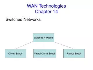
Chapter 10 WAN MOKHDZANI WAN NOR HAIMI ROSYDI ZAKARIA AHMAD HUSNI MOHD SHAPRI. Processor Structure and Function. Processor Organization. Fetch instruction The processor reads an instruction from memory (register, cache, main memory) Interpret instruction

E N D
Chapter 10WAN MOKHDZANI WAN NOR HAIMIROSYDI ZAKARIAAHMAD HUSNI MOHD SHAPRI Processor Structure and Function
Processor Organization Fetch instruction The processor reads an instruction from memory (register, cache, main memory) Interpret instruction The instruction is decoded to determine what action is required Fetch data The execution of an instruction may require reading data from memory or an I/O module Process data The execution of an instruction may require performing some arithmetic or logical operation on data Write data The results of an execution may require writing data to memory or an I/O module In order to do these things the processor needs to store some data temporarily and therefore needs a small internal memory Processor Requirements:
Register Organization • Within the processor there is a set of registers that function as a level of memory above main memory and cache in the hierarchy • The registers in the processor perform two roles: User-Visible Registers Control and Status Registers • Enable the machine or assembly language programmer to minimize main memory references by optimizing use of registers • Used by the control unit to control the operation of the processor and by privileged operating system programs to control the execution of programs
Control and Status Registers Program counter (PC) Contains the address of an instruction to be fetched Instruction register (IR) Contains the instruction most recently fetched Memory address register (MAR) Contains the address of a location in memory Memory buffer register (MBR) Contains a word of data to be written to memory or the word most recently read Four registers are essential to instruction execution:
Review Questions • Critique the user-visible registers and control/status registers. • 2. Summarize the general-purpose registers with their examples.
User-visible registers: Enable the machine- or assembly language programmer to minimize main-memory references by optimizing use of registers. Control and status registers: Used by the control unit to control the operation of the CPU and by privileged, operating system programs to control the execution of programs. General Purpose Register: These registers are used along with other registers to perform arithmetic & logical operations. These registers are also used for data movement purposes inside the computer. Ex: Segment pointers, Index registers, Stack pointer
Review Question Given the following program: MOV AL, 11111101B; MOV BL, 00000011B; NOT AL ADD AL,BL; Evaluate the contents of AL, BL and the Processor Status Register (Flags).
Answer • 00000010+00000011=00000101 • Carry = 0; Zero = 0; Overflow = 0; Sign = 0; Even parity = 1; Half-carry= 0. • Even parity indicates that there is an even number of 1s in the result.
Example Microprocessor Register Organizations
Additional Stages • Fetch instruction (FI) • Read the next expected instruction into a buffer • Decode instruction (DI) • Determine the opcode and the operand specifiers • Calculate operands (CO) • Calculate the effective address of each source operand • This may involve displacement, register indirect, indirect, or other forms of address calculation • Fetch operands (FO) • Fetch each operand from memory • Operands in registers need not be fetched • Execute instruction (EI) • Perform the indicated operation and store the result, if any, in the specified destination operand location • Write operand (WO) • Store the result in memory
If the six stages are not of equal duration, there will be some waiting involved at various pipe- line stages. Another difficulty is the conditional branch instruction, which can invalidate several instruction fetches. A similar unpredictable event is an interrupt. Figure 14.11 illustrates the effects of the conditional branch, using the same program as Figure 14.10. Assume that instruction 3 is a conditional branch to instruction 15. Until the instruction is executed, there is no way of knowing which instruction will come next.
The Effect of a Conditional Branch on Instruction Pipeline Operation
Review Question Now consider the timing diagram of Figure 14.10. Assume that there is only a 2 stage pipeline (Fetch & Execute). With the aid of a timing diagram, deduce the time units needed for four instructions.
Pipeline Performance The cycle time τof an instruction pipeline is the time needed to advance a set of instructions one stage through the pipeline. (Example: each column in Figure 14.10 and 14.11 represents one cycle time. The cycle time can be determined as: τi= time delay of the circuitry in the ith stage of the pipeline τm = maximum stage delay (delay through stage which experiences the largest delay) k= number of stages in the instruction pipeline d = time delay of a latch, needed to advance signals and data from one stage to the next
Pipeline Performance (cont) Suppose that n instructions are processed, with no branches. Let be the total time required for a pipeline with k stages to execute n instructions. Then Now consider a processor with equivalent functions but no pipeline, and assume that the instruction cycle time is . The speedup factor for the instruction pipeline compared to execution without the pipeline is defined as
Review Question Evaluate the speedup factor for the instruction pipeline compared to execution without the pipeline based on Figure 14.10.
ResourceHazards A resource hazard occurs when two or more instructions that are already in the pipeline need the same resource The result is that the instructions must be executed in serial rather than parallel for a portion of the pipeline A resource hazard is sometimes referred to as a structural hazard
RAW Hazard Data Hazards A data hazard occurs when there is a conflict in the access of an operand location
Types of Data Hazard • Read after write (RAW), or true dependency • An instruction modifies a register or memory location • Succeeding instruction reads data in memory or register location • Hazard occurs if the read takes place before write operation is complete • Write after read (WAR), or antidependency • An instruction reads a register or memory location • Succeeding instruction writes to the location • Hazard occurs if the write operation completes before the read operation takes place • Write after write (WAW), or output dependency • Two instructions both write to the same location • Hazard occurs if the write operations take place in the reverse order of the intended sequence
Control Hazard • Also known as a branch hazard • Occurs when the pipeline makes the wrong decision on a branch prediction • Brings instructions into the pipeline that must subsequently be discarded • Dealing with Branches: • Multiple streams • Prefetch branch target • Loop buffer • Branch prediction • Delayed branch
Prefetch Branch Target When a conditional branch is recognized, the target of the branch is prefetched, in addition to the instruction following the branch Target is then saved until the branch instruction is executed If the branch is taken, the target has already been prefetched IBM 360/91 uses this approach
Loop Buffer • Small, very-high speed memory maintained by the instruction fetch stage of the pipeline and containing the n most recently fetched instructions, in sequence • Benefits: • Instructions fetched in sequence will be available without the usual memory access time • If a branch occurs to a target just a few locations ahead of the address of the branch instruction, the target will already be in the buffer • This strategy is particularly well suited to dealing with loops • Similar in principle to a cache dedicated to instructions • Differences: • The loop buffer only retains instructions in sequence • Is much smaller in size and hence lower in cost
Branch Prediction • Various techniques can be used to predict whether a branch will be taken: • Predict never taken • Predict always taken • Predict by opcode • Taken/not taken switch • Branch history table • These approaches are static • They do not depend on the execution history up to the time of the conditional branch instruction • These approaches are dynamic • They depend on the execution history
Summary Chapter 14 Processor Structure and Function • Processor organization • Register organization • User-visible registers • Control and status registers • Instruction cycle • The indirect cycle • Data flow • The x86 processor family • Register organization • Interrupt processing • Instruction pipelining • Pipelining strategy • Pipeline performance • Pipeline hazards • Dealing with branches • Intel 80486 pipelining • The Arm processor • Processor organization • Processor modes • Register organization • Interrupt processing