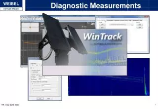
Diagnostic Measurements
Diagnostic Measurements. Agenda. Test and Verification Measurements Trigger testing Background noise and unwanted signals Known targets and radar beacons Target dynamics Possible bad aspect angles Angular velocities and ”dangerous” trajectory Measurement Setup Correction

Diagnostic Measurements
E N D
Presentation Transcript
Diagnostic Measurements TR-1102 AUG 2013
Agenda • Test and Verification Measurements • Trigger testing • Background noise and unwanted signals • Known targets and radar beacons • Target dynamics • Possible bad aspect angles • Angular velocities and ”dangerous” trajectory • Measurement Setup Correction • Target catch point • Initial look point vs. predicted • Velocity, Azimuth and Elevation trigger delays • Side-lobe tracking • Incorrect measurement settings • Max velocity and FFT Points • RTP processing parameters TR-1102 AUG 2013
Test and Verification Measurements • Trigger testing • Once measurement setup is completed test the trigger system. A missed trigger will mean a missed measurement. • Arm the trigger in use and let it wait for a trigger for at least 1 minute, to ensure that the system does not receive any false triggers • Trigger the system through the correct trigger device (i.e. Using a flashlight on the flash detector) • Consider any possible sources of false triggers that will only be evident once real testing begins. (i.e. Using the Weibel VHF trigger link for the trigger system and every time the commander does a countdown over radio the system is triggered) TR-1102 AUG 2013
Background Noise Measurements • It is always a good to have knowledge of the background noise of the current setup. • Possible background noise measurements are performed in high and low elevation • Panning the radar around to look for any possible noisy areas around the radar • This method of operation also ensures that the operator quickly realizes if something is wrong (i.e. If background noise level has increased by 20dB day to day) TR-1102 AUG 2013
Unwanted Signals • When performing background noise measurements unknown/unwanted signals may appear; such as: • Fixed frequency noise (often related to other technical equipment) • Noise burst (often seen over bodies of water or large mechanical equipment i.e. windmills) • Consider two aspect when seeing unknown/unwanted signals • Will it directly affect the measurement i.e. If the targets velocity profile crosses a fixed frequency noise • Will it indirectly affect the measurement i.e. by masking the target in areas of increase background noise or possible noise bursts • Unknown/unwanted signals should always be attempted removed • Fixed frequency noise can be located by simply trying to turn off equipment located close to the radar (ventilators, surveillance cameras etc.) • Noisy areas are only possible to limit by either changing radar location or avoiding these areas during measurements Ventilator Noise TR-1102 AUG 2013
Target Dynamics • Always try to consider different aspects of target shape, possible bad aspect angles and angular velocities before measurements • If possible evaluate previously measured data of similar target and mark specific areas of bad aspect angles and similar problems • From target prediction radar position can be evaluated in regards to the required pedestal angular velocities TR-1102 AUG 2013
Measurement Setup Correction • Target Catch Points • Evaluate the predicted catch point and delays vs. predicted trajectory or the first measurement • Ensure that the angular velocity is not to high as a requirement for higher angular velocity makes for ”unsafe” measurements Catch Point TR-1102 AUG 2013
Measurement Setup Correction • Side-lobe tracking • Often a target goes through several side-lobes before entering the main lobe • It is always mission critical that the radar does not start track the target while it is in these lobes • After first measurement it is always a good idea to evaluate the data and ensure that the system is not close to a ”bad” setup Target going through several side-lobes Antenna catch position is off by roughly 4 degrees; which should be corrected TR-1102 AUG 2013
Measurement Setup Correction • Incorrect measurement settings • Max Velocity set to low simply prevents the radar from tracking any target above the set value. • FFT points set to high for an early acquisition which requires high angular velocity from the system may result in to few measurement points to support the pedestal fitting • RTP processing parameters • If possible the RTP settings should be tested using the playback mode before any measurement is started • If the RTP failed to acquire a target that passed the catch point a expected; this recorded data can be used to test the settings either using the playback mode or doing post-processing and finding better parameters TR-1102 AUG 2013