Comprehensive Guide to Hardware Timers in Coldfire Processor
Learn the functions and applications of hardware timers in Coldfire processor, from basic units to advanced features like waveform generation and pulse width measurement. Includes programming examples.

Comprehensive Guide to Hardware Timers in Coldfire Processor
E N D
Presentation Transcript
Timers in Coldfire Processor Computer Science & Engineering DepartmentArizona State University Tempe, AZ 85287 Dr. Yann-Hang Leeyhlee@asu.edu(480) 727-7507
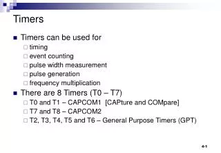
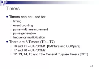
General Purpose Timer • The basic unit – counter (up or down) • a clock source • generate timing events (interrupts or timer output) • if overflow or reach 0 • if match with a preset value • measure time – read counter values (captured) • free running, reset or reload, compare clock (external or internal) binary counter control circuit
clock binary counter load event interrupt or ready flag edge detection input capture register Measurement • Input-capture : identify the moment that an event occurs • latch the counter value when triggered • CPU can read the value later • Output compare : control the timing of output bit • CPU sets a value in output compare register • compare with counter every clock cycle • if equal, send an output signal • External event counting • Measuring elapsed time, pulse width, frequency, and period
Hardware Timer • Typical approach – • hardware unit generates an interrupt per unit of time (e.g. millisecond) • Avoid overflow with a software counter (in memory) – incremented when interrupts • assume the input clock of 2MHz (0.5x10⁻³ ms) • set a compare counter to 1999 • start counting with the input clock and, when equals to the compare register • interrupt • restart the counter from 0 interrupt or toggle output = binary counter input clock (2MHz) restart compare register (1999)
Delay Function using DMA Timer • Initialize a timer and input frequency • Set up a compare value • Check for flag or wait for interrupt
DMA Timer • Control and status registers • mode register: #define MCF_DTIM3_DTMR *(vuint16*)(&__IPSBAR[0x0004C0])) • extended mode register • event register • reference register: for comparison • capture register: save counter value on capture event • counter register: counting
Fucntion cpu_pause void cpu_pause_m(int usecs) { /* Enable the DMA Timer 3 */ MCF_DTIM3_DTRR = (usecs - 1); MCF_DTIM3_DTER = MCF_DTIM_DTER_REF; // 0x02 MCF_DTIM3_DTMR = 0 | MCF_DTIM_DTMR_PS(sys_clk_khz / 1000) | MCF_DTIM_DTMR_ORRI // 0x0010 | MCF_DTIM_DTMR_FRR // 0x0008 | MCF_DTIM_DTMR_CLK_DIV1 // 0x0002 | MCF_DTIM_DTMR_RST; // 0x0001 while ((MCF_DTIM3_DTER & MCF_DTIM_DTER_REF) == 0) {}; /* Disable the timer */ MCF_DTIM3_DTMR = 0; }
capture count1 capture count2 Pulse Width Measurement • Capture counter values on edges • Read the difference to know the width • (count2-count1)/(timer frequency) • If the pulse is much longer, counter may overflow • interrupts on overflows • use software counter to count number of overflows.
Waveform Generator • Duty cycle : (pulse duration)/(clock period) • 50% -- square wave • Free-running or reset on compare event • Use DMA timer to generate a square wave of 1KHz based on an input clock is 40MHz— • Pin assignment of DMA timer 0 • Toggle output every 500ms • Mode register: CE, OM, ORPI, FRR, CLK, RST • Reference register: DTRR • 500ms = 1/40MHz * (prescale+1) * (DTRR+1)
PWM in 5211 • 4 PWM outputs • 8 channels • Counter (8 bits) • Period/duty • Even+odd channels 16 bit pwm • 4 clock sources • A, SA, B, SB
PWM in 5211 • Initialization MCF_GPIO_PTAPAR = 0 | MCF_GPIO_PTAPAR_PTAPAR0(3); MCF_PWM_PWMPOL = 0 | MCF_PWM_PWMPOL_PPOL1; MCF_PWM_PWMCLK = 0|MCF_PWM_PWMCLK_PCLK1; MCF_PWM_PWMPRCLK = PRE_SCALE; MCF_PWM_PWMSCLA = SCALE; MCF_PWM_PWMPER1 = 255; • Set duty cycle MCF_PWM_PWMDTY(channel) = duty_cycle; • Enable pwm MCF_PWM_PWME = 0|MCF_PWM_PWME_PWME1