Networking Fundamentals Refresher Workshop
This workshop revises core concepts and ensures consistent terminology usage for building networks at Layers 1, 2, 3, and 4. Topics include equipment types, protocols, addressing, and network design guidelines.

Networking Fundamentals Refresher Workshop
E N D
Presentation Transcript
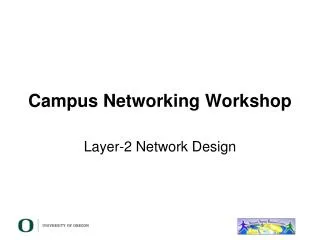
Campus Networking Workshop Networking Fundamentals Refresher
Objectives • To revise the core concepts • To ensure we are using the same terminology
What is this? 7 Application 6 Presentation 5 Session 4 Transport 3 Network 2 Link 1 Physical
Layer 1: Physical Layer • Transfers a stream of bits • Defines physical characteristics • Connectors, pinouts • Cable types, voltages, modulation • Fibre types, lambdas • Transmission rate (bps) • No knowledge of bytes or frames 101101 Examples of Layer 1 technologies and standards?
Types of equipment • Layer 1: Hub, Repeater, Media Convertor • Works at the level of individual bits • All data sent out of all ports • Hence data may end up where it is not needed
Building networks at Layer 1 • What limits do we hit? Rpt Rpt Rpt Hub Hub Hub
Layer 2: (Data)Link Layer • Organises data into frames • May detect transmission errors (corrupt frames) • May support shared media • Addressing (unicast, multicast) – who should receive this frame • Access control, collision detection • Usually identifies the layer 3 protocol being carried
Example Layer 2: SLIP • That's it! Flag Information Flag
Example Layer 2: PPP • Also includes link setup and negotiation • Agree link parameters (LCP) • Authentication (PAP/CHAP) • Layer 3 settings (IPCP) Flag Protocol Information CRC Flag
Example Layer 2: Ethernet Header • MAC addresses • Protocol: 2 bytes • e.g. 0800 = IPv4, 0806 = ARP, 86DD = IPv6 • Preamble: carrier sense, collision detection Dest MAC Src MAC Proto Information CRC Gap Preamble
Types of equipment (contd) • Layer 2: Switch, Bridge • Receives whole layer 2 frames and selectively retransmits them • Learns which MAC addr is on which port • If it knows the destination MAC address, will send it out only on that port • Broadcast frames must be sent out of all ports, just like a hub • Doesn’t look any further than L2 header
Switch Switch Switch Building networks at Layer 2 • What limits do we hit?
Layer 3: (Inter)Network Layer • Connects Layer 2 networks together • Forwarding data from one network to another • Universal frame format (datagram) • Unified addressing scheme • Independent of the underlying L2 network(s) • Addresses organised so that it can scale globally (aggregation) • Identifies the layer 4 protocol being carried • Fragmentation and reassembly
Example Layer 3: IPv4 Datagram Header • Src, Dest: IPv4 addresses • Protocol: 1 byte • e.g. 6 = TCP, 17 = UDP (see /etc/protocols) hdr csum Version, length, flags, fragments TTL Src IP Dest IP Proto Information
Types of equipment (contd) • Layer 3: Router • Looks at the dest IP in its Forwarding Table to decide where to send next • Collection of routers managed together is called an “Autonomous System” • The forwarding table can be built by hand (static routes) or dynamically • Within an AS: IGP (e.g. OSPF, IS-IS) • Between ASes: EGP (e.g. BGP)
Switch Switch Hub Hub Hub Hub Traffic Domains Router Broadcast Domain Collision Domain
Network design guidelines • No more than ~250 hosts on one subnet • Implies: subnets no larger than /24 • Campus guideline: one subnet per building • More than one may be required for large buildings
Layer 4: Transport Layer • Identifies the endpoint process • Another level of addressing (port number) • May provide reliable delivery • Streams of unlimited size • Error correction and retransmission • In-sequence delivery • Flow control • Or might just be unreliable datagram transport
Example Layer 4: UDP Header • Port numbers: 2 bytes • Well-known ports: e.g. 53 = DNS • Ephemeral ports: ≥1024, chosen dynamically by client Src Port Dst Port Len Checksum Information
Layers 5 and 6 • Session Layer: long-lived sessions • Re-establish transport connection if it fails • Multiplex data across multiple transport connections • Presentation Layer: data reformatting • Character set translation • Neither exist in the TCP/IP suite: the application is responsible for these functions
Layer 7: Application layer • The actual work you want to do • Protocols specific to each application • Examples?
Encapsulation • Each layer provides services to the layer above • Each layer makes use of the layer below • Data from one layer is encapsulated in frames of the layer below
Encapsulation in action • L4 segment contains part of stream of application protocol • L3 datagram contains L4 segment • L2 frame contains L3 datagram in its data portion L2 hdr L3 hdr L4 hdr Application data
For discussion • Can you give examples of equipment which operates at layer 4? At layer 7? • At what layer does a wireless access point work? • What is a “Layer 3 switch”? • How does traceroute find out the routers which a packet traverses?
Addressing at each layer • What do the addresses look like? • How do they get allocated, to avoid conflicts? • Examples to consider: • L2: Ethernet MAC addresses • L3: IPv4, IPv6 addresses • L4: TCP and UDP port numbers
IPv4 addresses • 32-bit binary number • How many unique addresses in total? • Conventionally represented as four dotted decimal octets 10000000110111111001110100010011 128 . 223 . 157 . 19
Hierarchical address allocation IANA 0.0.0.0 255.255.255.255 RIR LIR End User
Prefixes • A range of IP addresses is given as a prefix, e.g. 192.0.2.128/27 • In this example: • How many addresses are available? • What are the lowest and highest addresses? 32 bits Prefix /27 Host 27 bits 5 bits
Prefix calculation 192 . 0 . 2 . 128 11000000000000000000001010000000 Prefix length /27 First 27 bits are fixed Lowest address: 11000000000000000000001010000000 192 . 0 . 2 . 128 Highest address: 11000000000000000000001010011111 192 . 0 . 2 . 159
IPv4 “Golden Rules” • All hosts on the same L2 network must share the same prefix • All hosts on the same subnet have different host part • Host part of all-zeros and all-ones are reserved 32 bits Prefix /27 Host 27 bits 5 bits
Golden Rules for 192.0.2.128/27 • Lowest 192.0.2.128 = network address • Highest 192.0.2.159 = broadcast address • Usable: 192.0.2.129 to 192.0.2.158 • Number of usable addresses: 32 - 2 = 30
Exercises • Network 10.10.10.0/25 • How many addresses in total? • How many usable addresses? • What are the lowest and highest usable addresses? • Network 10.10.20.0/22 • How many addresses in total? • How many usable addresses? • What the the lowest and highest usable addresses?
An edge case • How many usable addresses in a /30 prefix? • What is this used for? • (Note: modern routers support /31 for this purpose to reduce IP address wastage)
Netmask • Netmask is just an alternative (old) way of writing the prefix length • A '1' for a prefix bit and '0' for a host bit • Hence N x 1's followed by (32-N) x 0's /27 = 11111111111111111111111111100000 255 . 255 . 255 . 224
Subnetting • Since each L2 network needs its own prefix, then if you route more than one network you need to divide your allocation • Ensure each prefix has enough IPs for the number of hosts on that network End User Allocation Subnets
Subnetting Example • You have been given 192.0.2.128/27 • However you want to build two Layer 2 networks and route between them • The Golden Rules demand a different prefix for each network • Split this address space into two equal-sized pieces • What are they?
Subnetting /27 192 . 0 . 2 . 128 11000000000000000000001010000000 Move one bit from host part to prefix We now have two /28 prefixes 11000000000000000000001010000000 192 . 0 . 2 . 128 Second prefix: 11000000000000000000001010010000 192 . 0 . 2 . 144
Check correctness • Expand each new prefix into lowest and highest • Ranges should not overlap • 192.0.2.128/28 • Lowest (network) = 192.0.2.128 • Highest (broadcast) = 192.0.2.143 • 192.0.2.144/28 • Lowest (network) = 192.0.2.144 • Highest (broadcast) = 192.0.2.159 • How many usable addresses now?
Aggregation tree • Continue to divide prefixes as required • Can visualize this as a tree /24 /25 /25 /26 /26 /27 /27 /27 /27
IPv6 addresses • 128-bit binary number • Conventionally represented in hexadecimal – 8 words of 16 bits, separated by colons 2001:0468:0d01:0103:0000:0000:80df:9d13 • Leading zeros can be dropped • One contiguous run of zeros can be replaced by :: 2001:468:d01:103::80df:9d13
Hexadecimal 0000 0 0001 1 0010 2 0011 3 0100 4 0101 5 0110 6 0111 7 1000 8 1001 9 1010 a 1011 b 1100 c 1101 d 1110 e 1111 f 0000 = 0000000000000000 ffff = 1111111111111111
IPv6 rules • With IPv6, every network prefix is /64 • (OK, some people use /127 for P2P links) • The remaining 64 bits can be assigned by hand, or picked automatically • e.g. derived from NIC MAC address • There are special prefixes • e.g. link-local addresses start fe80:: • Total available IPv6 space is ≈ 261 subnets • Typical end-user allocation is /48 (or /56)
IPv6 addressing • How many /64 networks can you build given a /48 allocation? network prefix host ID /64 /64 /48 assigned address space network ID
IPv6 addressing • You are assigned 2001:db8:123::/48 • 2001:0db8:0123:0000:0000:0000:0000:0000 • Lowest /64 network? • 2001:db8:123:0000::/64 • written simply 2001:db8:123::/64 • Highest /64 network? • 2001:db8:123:ffff::/64
Ways to allocate the host part • Do it automatically from MAC address – "stateless autoconfiguration" • Not recommended for servers: if you change the NIC then the IPv6 address changes! • Can number sequentially from 1, or use the last octet of the IPv4 address • Or embed the whole IPv4 address • e.g. 2607:8400:2880:4::80df:9d13 • 80df9d13 hex = 128.223.157.19 in decimal • Can write 2607:8400:2880:4::128.223.157.19
Notes on IPv6 • Broadly similar to IPv4 • "ARP" is replaced by "NDP" • IPv6 client configuration options • Stateless autoconf (router advertisements) • Stateless autoconf + stateless DHCPv6 • Stateful DHCPv6 • Interfaces typically get both a link-local address and one or more routable prefixes • "Dual stack" = v4 and v6 side-by-side
Debugging Tools • What tools can you use to debug your network: • At layer 1? • At layer 2? • At layer 3? • Higher layers?
Other pieces • What is MTU? What limits it? • What is ARP? • Where does it fit in the model? • What is ICMP? • Where does it fit in the model? • What is NAT? PAT? • Where do they fit in the model? • What is DNS? • Where does it fit in the model?