Download

1 / 7
70 likes | 84 Vues
This project addresses the issue of oil mist carry-over in the hydrogen sample line at the Fort St. Vrain Combined Cycle Station in Platteville, Colorado. The condensation of oil in the hydrogen control panel affects the calibration of purity analyzers, potentially compromising safety and automatic generator purge. The modification includes the removal of existing knock-out pots, addition of smaller drip legs with blow-down valves, and installation of prefilters and coalescing filters. All connections are leak tested to ensure optimal performance.

E N D
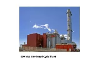
HYDROGEN SAMPLE LINE MODIFICATION at Fort St. Vrain Combined Cycle Station Platteville, Colorado
Problem: Oil mist carry over in hydrogen sample from seal drain enlargement tanks condenses as it cools in hydrogen control panel. • Evidence of this is oil bubbling in the sample flow meters and / or total flow meter. • Calibration of purity analyzers is then in question, and operation is potentially unsafe and / or possibility of automatic generator purge and turbine trip.
Modification performed during combustion inspection with the generator purged to CO2, and includes the following: • Removal of existing knock-out pots • Adding smaller drip legs with blow down valves • Adding prefilters • Adding coalescing filters with blow down valves exterior to enclosure • All connections (welded and Swaglok fittings) leak tested to 150 psig.
Route sample inside-to-outside through the prefilter, and outside-to-inside through the coalescer.
Existing isolation valves Coalescer Prefilter New drip leg: 1” x 15” pipe
FILTER PARTS Headline Filters Housing: Model 148 Elements for both prefilter and coalescer: 25-178-CC www.ufs-hf.com. 1-800-311-5561 Purchased through: Webster & Assoc Denver, CO 303-773-8989