Download
1 / 1
10 likes | 153 Vues
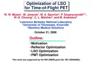
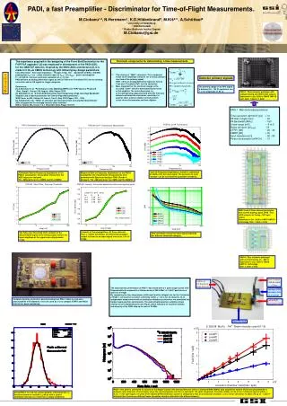
Time Outputs LAN-K5 cable ~2.1m. Cables to SC Diamond Pixel Detector. Interface PCB +5V,GND,THR connections. LVDS-PECL Converter PCB. PADI test PCB. PADI, a fast Preamplifier - Discriminator for Time-of-Flight Measurements.

E N D
Time Outputs LAN-K5 cable ~2.1m Cables to SC Diamond Pixel Detector Interface PCB +5V,GND,THR connections LVDS-PECL Converter PCB PADI test PCB PADI, a fast Preamplifier - Discriminator for Time-of-Flight Measurements. M.Ciobanu1,2, N.Herrmann1, K.D.Hildenbrand2, M.Kiš2,3 , A.Schüttauf2 1 University of Heidelberg 2 GSI-Darmstadt 3 Rudjer Boskovic Institut Zagreb M.Ciobanu@gsi.de • The experience acquired in the designing of the Front-End Electronics for the • FOPI-ToF upgrade [1,2] was employed in development of the PADI-ASIC • for the CBM-ToF detector. Inspired by the NINO-ASIC architecture [3], it is • made in 0.18 m CMOS technology with following key design parameters: • fully differential - 50 input impedance - PA gain of Gp> 100 - bandwidth of BWp> 300 MHz • peaking time tpk< 1ns - noise related to input of VN-IN < 25 VRMS - power consumption • P < 30 mW/ch - intrinsic electronic resolution of tE <15 ps • PADI delivers an analog differential signal as well as Time-over-Threshold (ToT) for the slewing • correction and an OR signal for trigger purposes. • References: • [1] A.Schuttauf et al, "Performance of the Multistrip-MRPCs for FOPI",Nuclear Physics B • (Proc. Suppl.), Volume 158, August, 2006, Pages 52-55. • [2] M.Ciobanu et al, "A Front-End Electronics Card Comprising a High Gain/High Bandwidth • Amplifier and a Fast Discriminator for Time-of-Flight Measurements", • IEEE Trans. on NS, Volume 54, Issue 4, Part 3, Aug. 2007 Pages:1201 - 1206 • [3] F.Anghinolfi et al, "NINO: an ultra-fast and low-power front-end amplifier/discriminator • ASIC designed for the multigap resistive plate chamber" • NIM A, Volume 533, Issues 1-2, 1 November 2004, Pages 183-187 Dominant components for deteriorating a time measurements • The slewing or “Walk” correction: This component • is due to the amplitude variation for a nearly constant • rise time of the primary signal. • PADI offers an analog differential signal as well as • Time-over-Threshold (ToT) for this correction • More important for the electronic design is the • so called "Jitter" which is dominated by the noise • of the amplifier. The noise dispersion (n) • at the falling/rising edge projected onto the time-axis • allows to estimate the electronics resolution. In • general, there exist an additive term (δt) which • is due to the discriminator and time digitizer. Detector primary signals Motivation The primary charge of an RPC signal is between 25 - 100 fC equivalent to a 1- 4 mV amplitude (in 50 ) PADI-1: Three channel prototype with voltage biasing and differential outputs Submitted in July 2006 in CMOS UMC18 tech. Size: 1.5mm x 1.5mm • PADI-1 Main technical parameters: • Time resolution (@10mV) [ps] < 10 • PA Gain (single input) ~ 60 • PA Bandwidth [MHz] ~ 180 • Linear range [mV] ~ -5 to 5 • Noise (at input) [µVRMS] ~32 • CTRR [dB] ~ 26 - 40 • CMRR [dB] > 40 • Input impedance [] ~ 48 - 58 • Power consumption [mW/Ch] ~ 31 Gain-to-Frequency dependence, tested in a dynamics of 40dB of the AC input signal. The presence of local "bumps" can be correlated to a possible instabilitiy. Simulated Gain-to-Frequency dependence of the PADI-1 preamplifier; the parasitic effects from the ASIC layout are included. The -3dB points are fL=14MHz and fH =240MHz. Measured Gain-to-Frequency dependence of the PADI-1 preamplifier; the transmission measurements were performed with Spectrum Analyzer FSH3 (Rohde & Schwarz). The -3dB points are fL=14MHz and fH=180MHz. PADI-2 and 3: Four channel prototypes with current biasing, quasi LVDS / true LVDS outputs for timing , OR input, output Submitted in Oct. 2008 in CMOS UMC18 technology. Size: 1.5mm x 3mm Linearity of the preamplifiers: All three channels have a similar sensitivity; the differential analogue output is linear for an input signal interval of -5 to +5 mVpk. The Time-over-Threshold (ToT) variation of the discriminated signal at the timing output reflects the input amplitude of the signal over a big dynamic range. Time resolution versus the input signal amplitude (for different threshold voltages). PADI-4: Four channels prototype with current biasing, ZIN ~680 Submitted in Oct. 2008 in CMOS UMC18 technology. Size: 1.5mm x 3mm The experimental performance of PADI-1 was tested with a 4 pixel single-crystal CVD Diamond detector exposed to a Carbon beam of 356*A MeV of 1.5x10⁸ particles in a spill of 2 s length. By comparing the time dependence within spill and the integral rate for the 3 channels of PADI-1, we found an excellent uniformity within +/- 0.2 % for all channels. In an independent measurement with an ionization chamber as reference, we monitored the Carbon beam position and intensity. The yield of both detectors exhibits a linear relation for all 3 diamond pixels (see Fig.2), which indicates an excellent stability and linearity of the PADI chip up to rates of 75 MHz Complete detector-electronics board including two PADI-1chips to read out a polycrystalline CVD diamond. It is to be used as a very compact START and HALO detector for beam monitoring. PADI-1 test plate is connected to 3 pixels of the Single Crystal CVD diamond detector and to a standard NIM-CAMAC data acquisition system which was programmed to measure rates [hits/ms]. The left figure show the rate histograms over the 2 s spill (with 110 spills integrated). The total number of hits in the 3 channels agrees within +/-0.2%. In the right figure, the yield of the diamond/PADI detection system is compared to that of an ionization chamber; a very linear correlation is observed up to ~1.35x10⁸ hits/spill (the 3 pixels see different beam intensities which is reflected in the different slopes). Using PADI-1 to read out a polycrystalline CVD diamond in a heavy-ion beam we reached td<45 ps with a plastic scintillator detector as a reference (t<62ps combined).