Lecture 4. ARM Instructions #1
ECM586 Special Topics in Embedded Systems. Lecture 4. ARM Instructions #1. Prof. Taeweon Suh Computer Science Education Korea University. ARM Instruction Overview. ARM is a RISC machine, so the instruction length is fixed In the ARM mode, the instructions are 32-bit wide

Lecture 4. ARM Instructions #1
E N D
Presentation Transcript
ECM586 Special Topics in Embedded Systems Lecture 4. ARM Instructions #1 Prof. Taeweon Suh Computer Science Education Korea University
ARM Instruction Overview • ARM is a RISC machine, so the instruction length is fixed • In the ARM mode, the instructions are 32-bit wide • In the Thumb mode, the instructions are 16-bit wide • Most ARM instructions can be conditionally executed • It means that they have their normal effect only if the N (Negative), Z (Zero), C (Carry) and V (Overflow) flags in the CPSR satisfy a condition specified in the instruction • If the flags do not satisfy this condition, the instruction acts as a NOP (No Operation) • In other words, the instruction has no effect and advances to the next instruction
ARM Instruction Format Arithmetic and Logical Instructions Memory Access Instructions (Load/Store) Branch Instructions Software Interrupt Instruction
ARM Instructions – ADD • ADD will add the two operands, placing the result in the destination register. • Use S suffix to update conditional field • For example, to update the Carry flag • Operand 1 is a register, operand 2 can be a register, shifted register, or an immediate value: • Examples • ADD R0, R1, R2 ; R0 = R1 + R2 • ADD R0, R1, #256 ; R0 = R1 + 256 • ADDS R0, R2, R3,LSL#1 ; R0 = R2 + (R3 << 1) and update flags • The addition may be performed on signed or unsigned numbers.
Overflow/Underflow • Overflow/Underflow: • The answer to an addition or subtraction exceeds the magnitude that can be represented with the allocated number of bits • Overflow/Underflow is a problem in computers because the number of bits to hold a number is fixed • For this reason, computers detect and flag the occurrence of an overflow/underflow. • Detection of an overflow/underflow after the addition of two binary numbers depends on whether the numbers are considered to be signed or unsigned
Overflow/Underflow in Unsigned Numbers • When two unsigned numbers are added, an overflowis detected from the end carry out of the most significant position • If the end carry is ‘1’, there is an overflow. • When two unsigned numbers are subtracted, an underflowis detected when the end carry is “0”
Subtraction of Unsigned Numbers • Unsigned number is either positive or zero • There is no sign bit • So, a n-bit can represent numbers from 0 to 2n - 1 • For example, a 4-bit can represent 0 to 15 (=24 – 1) • To declare an unsigned number in C language, • unsigned int a; • x86 allocates a 32-bit for “unsigned int” • Subtraction of unsigned integers (M, N) • M – N in binary can be done as follows: • M + (2n – N) = M – N + 2n • If M ≥ N, the sum produces an end carry, which is 2n • Subtraction result is zero or a positive number • If M < N, the sum does not produce an end carry since it is equal to 2n – (N – M) • Unsigned Underflow: subtraction result is negative and unsigned number can’t represent negative numbers
Overflow/Underflow in Signed Numbers • With signed numbers, an overflow/underflow can’t occur for an addition if one number is positive and the other is negative. • Adding a positive number to a negative number produces a result whose magnitude is equal to or smaller than the larger of the original numbers • An overflow may occur if two numbers are both positive in addition • When x and y both have sign bits of 0 (positive numbers) • If the sum has sign bit of 1, there is an overflow • An underflow may occur if two numbers are both negative in addition • When x and y both have sign bits of 1 (negative numbers) • If the sum has sign bit of 0, there is an underflow
Overflow/Underflow in Signed Numbers 8-bit Signed number addition 8-bit Signed number addition 10000001 (-127) 11111010 ( -6) -------------------- (-133) 01001000 (+72) 00111001 (+57) -------------------- (+129) What is largest positive number represented by 8-bit? What is smallest negative number represented by 8-bit? Slide from H.H.Lee, Georgia Tech
Overflow/Underflow in Signed Numbers • So, we can detect overflow/underflow with the following logic • Suppose that we add two k-bit numbers xk-1xk-2… x0 + yk-1yk-2… y0 = sk-1sk-2… s0 Overflow = xk-1yk-1sk-1 + xk-1yk-1sk-1 • There is an easier formula • Let the carry out of the full adder adding two numbers be ck-1ck-2… c0 Overflow = ck-1 + ck-2 • If a 0 (ck-2) is carried in, the only way that 1 (ck-1) can be carried out is if xk-1 = 1 and yk-1= 1 • Adding two negative numbers results in a non-negative number • If a 1 (ck-2) is carried in, the only way that 0 (ck-1) can be carried out is if xk-1 = 0 and yk-1= 0 • Adding two positive numbers results in a negative number
A2 B2 A1 B1 A A A A B B B B Full Adder Full Adder Full Adder Full Adder Cin Cin Cin Cin Cout Cout Cout Cout S S S S n-bit Adder/Subtractor Cn S2 S1 Overflow/ Underflow Cn-1 Overflow/Underflow Detection in Signed Numbers A3 B3 A0 B0 Carry Overflow/ Underflow S0 S3 Slide from H.H.Lee, Georgia Tech
Recap • Unsigned numbers • Overflow could occur when 2 unsigned numbers are added • An end carry of “1” indicates an overflow • Underflow could occur when 2 unsigned numbers are subtracted • An end carry of “0” indicates an underflow. • minuend < subtrahend • Signed numbers • Overflow could occur when 2 signed positive numbers are added • Underflow could occur when 2 signed negative numbers are added • Overflow flag indicates both overflow and underflow
Recap • Binary numbers in 2s complement system are added and subtracted by the same basic addition and subtraction rules as used in unsigned numbers • Therefore, computers need only one common hardware circuit to handle both types (signed, unsigned numbers) of arithmetic • The programmer must interpret the results of addition or subtraction differently, depending on whether it is assumed that the numbers are signed or unsigned.
ARM Flags • In general, computer has several flags (registers) to indicate state of operations such as addition and subtraction • N: Negative • Z: Zero • C: Carry • V: Overflow • We have only one adder inside a computer. • CPU does comparison of signed or unsigned numbers by subtraction using adder • CPU sets the flags depending on the result of operation • These flags provide enough information to judge that one is bigger than or less than the other?
ARM Instructions – Sub (Subtraction) • SUB subtracts operand 2 from operand 1, placing the result in the destination register. • Use S suffix to update conditional field • For example, to update the Carry flag • Operand 1 is a register, operand 2 can be a register, shifted register, or an immediate value: • Examples • SUB R0, R1, R2 ; R0 = R1 - R2 • SUB R0, R1, #256 ; R0 = R1 - 256 • SUB R0, R2, R3,LSL#1 ; R0 = R2 - (R3 << 1) and update flags • The subtraction may be performed on signed or unsigned numbers.
ARM Instructions – AND (Logical AND) • AND will perform a logical AND between the two operands, placing the result in the destination register • It is useful for masking the bits • Operand 1 is a register, operand 2 can be a register, shifted register, or an immediate value • Example • AND R0, R0, #3 ; Keep bits zero and one of R0 and discard the rest
ARM Instructions – EOR (Exclusive OR) • AND will perform a logical Exclusive OR between the two operands, placing the result in the destination register • It is useful for inverting certain bits • Operand 1 is a register, operand 2 can be a register, shifted register, or an immediate value • Example • EOR R0, R0, #3 ; Invert bits zero and one of R0
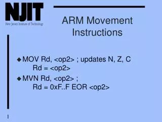
ARM Instructions – MOV (MOVE) • MOV loads a value into the destination register from another register, a shifted register, or an immediate value • Operand 1 is a register, operand 2 can be a register, shifted register, or an immediate value • Examples • MOV R0, R0; move R0 to R0, Thus, no effect • MOV R0, R0, LSL#3 ; R0 = R0 * 8 • MOV PC, R14; (R14: link register) Used to return to caller • MOVS PC, R14; PC <- R14 (lr), CPSR <- SPSR ; Used to return from interrupt or exception
ARM Instructions – B, BL • B (branch) and BL (branch with link) are used for conditional or unconditional branch • BL is used for the subroutine (procedure, function) call • To return from a subroutine, use • MOV PC, R14; (R14: link register) Used to return to caller • Branch target address • Sign-extend the 24-bit signed immediate (2’s complement) to 30-bits • Left-shift the result by 2 bits • Add it to the current PC (actually, PC+8) • Thus, the branch target could be ±32MB away from the current instruction
ARM Instructions – LDR (Load Register) • The LDR instruction loads a word from a memory location to a register • The memory location (addressing) is specified in a very flexible manner • Examples • LDR R0, [R1] // R0 <- [R1] • LDR R0, [R1, #16] // R0 <- [R1+16]
ARM Instructions – STR (Store Register) • The STR instruction stores a word to a memory location from a register • The memory location (addressing) is specified in a very flexible manner • Examples • STR R0, [R1] // [R1] <- R0 • STR R0, [R1, #16] // [R1+16] <- R0
LDR, STR - Single Data Transfer • Single data transfer instructions: STR, LDR • Format: • LDR R0, [address] // R0 ← [address] (32-bit data) • STR R0, [address] // [address] ← R0 (32-bit data) • [address] can be like below • STR R0, [Rbase] // [Rbase] ← R0 • Ex) STR R0, [R1] // [R1] ← R0 • STR R0, [Rbase, Rindex] // [Rbase+Rindex] ← R0 • Ex) STR R0, [R1, R2] // [R1+R2] ← R0 • STR R0, [Rbase, #index] // [Rbase+index] ← R0 • Ex) STR R0, [R1, #16] // [R1+16] ← R0 • STR R0, [Rbase, Rindex]! // [Rbase+Rindex] ← R0 // Rbase ← Rbase + Rindex • STR R0, [Rbase, #index]! // [Rbase+index] ← R0 // Rbase ← Rbase + Rindex • STR R0, [Rbase], Rindex // [Rbase] ← R0 // Rbase ← Rbase + index • STR R0, [Rbase, Rindex, LSL #n] // [Rbase+Rindex << n] ← R0
ARM Instructions – LDM, STM • The LDM (Load Multiple) instruction loads general-purpose registers from sequential memory locations • The STM (Store Multiple) instruction stores general-purpose registers to sequential memory locations
LDM, STM - Multiple Data Transfer • Multiple data transfer instructions (LDM and STM) are used to load and store multiple words of data from/to main memory • IA: Increment After • IB: Increment Before • DA: Decrement After • DB: Decrement Before • FA: Full Ascending (in stack) • FD: Full Descending (in stack) • EA: Empty Ascending (in stack) • ED: Empty Descending (in stack)
LDM, STM - Multiple Data Transfer • In multiple data transfer, the register list is given in a curly brackets {} • It doesn’t matter which order you specify the registers in • They are stored from lowest to highest • Examples • STMFD R13! {R0, R1} // R13 is updated • LDMFD R13! {R1, R0} // R13 is updated • A useful shorthand is “-” • It specifies the beginning and end of registers • Examples • STMFD R13!, {R0-R12} // R13 is updated appropriately • LDMFD R13!, {R0-R12} // R13 is updated appropriately
ARM Instructions – MSR, MRS • MSR: Move the value of a general-purpose register or an immediate constant to the CPSR or SPSR of the current mode • Examples: • MSR CPSR_all, R0 ; Copy R0 into CPSR • MSR SPSR_all, R0 ; Copy R0 into SPSR • MRS: Move the value of the CPSR or the SPSR of the current mode into a general-purpose register • Examples: • MRS R0, CPSR_all ; Copy CPSR into R0 • MRS R0, SPSR_all ; Copy SPSR into R0 • To change the operating mode, use the following code • Example: change to the supervisor mode • MRS R0,CPSR ; Read CPSR • BIC R0,R0,#0x1F ; Remove current mode with bit clear instruction • ORR R0,R0,#0x13 ; Substitute to the Supervisor mode • MSR CPSR_c,R0 ; Write the result back to CPSR
ARM Instructions – SWI (Software Interrupt) • The SWI instruction incurs a software interrupt • It is used by operating systems for system calls • 24-bit immediate value is ignored by the ARM processor, but can be used by the SWI exception handler in an operating system to determine what operating system service is being requested • Operations • CPSR is saved in SPSR • The next instruction’s PC of swi is saved in lr (R14: Link Register) • PC is changed to 0x0000_0008 • Example • swi 0x3 ; SPSR <- CPSR, ; lr (R14) <- PC after swi 0x3 • To return from the software interrupt, use • MOVS PC, R14; PC <- R14 (lr), CPSR <- SPSR
ARM Instructions – ADC (Add with Carry) • ADC will add the two operands, placing the result in the destination register. • It uses a carry bit, so can add numbers larger than 32 bits. • The following example will add two 128 bit numbers 128 bit result: registers 0, 1, 2, and 3 128 bit first operand: registers 4, 5, 6, and 7 128 bit second operand: registers 8, 9, 10, and 11 • ADDS R0, R4, R8 ; Add low words • ADCS R1, R5, R9 ; Add next word, with carry • ADCS R2, R6, R10 ; Add third word, with carry • ADCS R3, R7, R11 ; Add high word, with carry