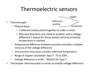
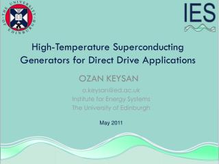
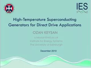
Thermoelectric Generators for Defense Applications
480 likes | 730 Vues
Thermoelectric Generators for Defense Applications. Primary Investigator: Daniel Allen Presenter: John C. Bass Sponsor: TACOM-ARDEC, Picatinny Arsenal TRI-SERVICE POWER EXPO 2003 16 July 2003. Agenda. Background in Thermoelectrics Picatinny Program Radio Isotope Program

Thermoelectric Generators for Defense Applications
E N D
Presentation Transcript
Thermoelectric Generators for Defense Applications Primary Investigator: Daniel Allen Presenter: John C. Bass Sponsor: TACOM-ARDEC, Picatinny Arsenal TRI-SERVICE POWER EXPO 2003 16 July 2003
Agenda • Background in Thermoelectrics • Picatinny Program • Radio Isotope Program • Milliwatt Generators • Molten Salt Generator • Watt Generator • Swedish Generator • Advanced Materials • Quantum Well Background • Recent Test Program • Summary
Picatinny SBIR Program Alternative Energy Source for Illumination • Mortar Site Illumination • Tritium Fueled RTG • Fossil Fueled Generator • Phase Change Heat Source • 1-2 Watt Generator • Battery Replacement • Generators Up to 25 Watts • Battery Charging • Logistic Fuel
Products HZ-14 HZ-20 800 milliWatt Modules for Micro Air Vehicle (MAV) 40 milliWatt Modules for Space Applications
Army’s Needs • Replacement for radioluminescent lamps • Battery replacement for small electronics associated with indirect fire weapons • Portable battery charger/battery replacement for soldier power
Phase I - Radioisotope Generator • In development for NASA/DOE for Mars surface weather station network • PHU: 1 W Pu238 • 40 mW output
Driving Factors • Use logistics fuel • Rugged, reliable, long life • Minimum specific power (W/kg) • Minimum specific energy (W-hr./kg) • Minimum specific volume (W-hr/1) • Low price, low operating & support cost • Environmentally friendly
Task 7 – Tritium Heat Source Development It was determined in the Phase I Option that radioisotopes appear not to be economically viable in this application, and so this task has been put on lowest priority.
Task 5 – Milliwatt Generator • Design (module) 300 mW • Actual power 360 mW • Generator output 5V • TH/TC 260ºC / 70ºC • Fuel consumption 40 mg//min • Input heat 33 W • Conversion efficiency 1.2% • Ref. module efficiency 4% • Est. burner efficiency 30%
Task 5 – Milliwatt Generator Generator #6 & #7 Generator #5B
Task 5 – Milliwatt Generator Generator #8
Task 5 – Milliwatt GeneratorGenerator #8 Features • “Hair Curler” butane burner • Graphite foam hot side heat exchanger • Aerogel insulation • Foam aluminum cold side heat exchanger • Swiss-made miniature efficient fan • Capability of 100 W-hr/kg
Power output, gross 4.5W Cooling fan 1.2W Combustion fan 0.06W Fuel pump 0.10W DC-DC converter 0.47W Power output, net 2.7W Fuel consumption 0.5ml/min Input heat 250W TH / TC 260ºC / 60ºC Fuel conversion efficiency, net 1.1% gross 1.8% Ref. module efficiency 4% Fuel energy to module 45% Tasks 1-4 – STEG-2
Tasks 1-4 – STEG “Slot” burner developed by Altex Technologies Corp.
Power output, gross 2.0W consumed to operate 0.5W Power output, net 1.5W Fuel consumption 0.33ml/min Input heat 165W TH / TC 260ºC / 65ºC Fuel conversion efficiency, net 0.9% gross 1.2% Tasks 1-4 – STEG-3
STEG as Charger ? 12V 24V 11V
Status of STEG • Voltage interface issue for “smart” (SMBus) battery charger circuits • Optimum stable operation • Electric start demonstration • Circuit board • Controls • Fuel tank • Unit Packaging
Task 6 – 15-20 Watt Generator • Burner being made and tested at Altex • Existing generator (originally propane-fueled) and power conditioning system being modified to fit
Task 8 – Heat of Phase Change(Molten Salt) Generator • Detailed generator design completed • Phase change material selected after further tests: LiNO3
Task 8 – Heat of Phase Change(Molten Salt) Generator Molten Salt Test
Candidate Compounds LiNO3 Melting point 250 to 264ºC Heat of fusion 367 J/g Volume required for 4 hours 119 cm3 FeCl3 Melting point 304 to 306ºC Heat of fusion 266 J/g Volume required for 4 hours 135 cm3 NaNO2 Melting point 271ºC Heat of fusion 217 J/g Volume required for 4 hours 221 cm3 Task 8 – Heat of Phase Change(Molten Salt) Generator
Task 8 – Heat of Phase Change(Molten Salt) Generator • Components fabricated/procured; partly assembled Complete Assembly
Priorities for Remaining Work • Final report • STEG prototype design • 15-20 W generator demonstration • Custom module spray-on leads test with mask • Run 300mW diesel-heated generator (Altex fuel cell project) • STEG delivery to Army • Finish and run Phase Change (Molten Salt) Generator
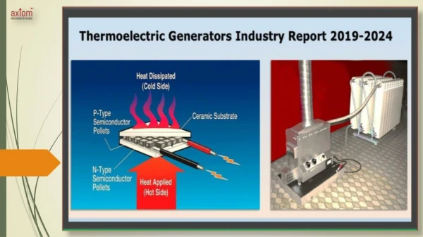
Quantum Well TE • Quantum-well confinement in multilayer films is achieved by the electron containment between adjacent barrier layers • Active layer (the well) is sandwiched between materials with band offset to form a barrier for the charge carriers • Improvement in Z from an increased Seebeck coefficient (α) and from an increase in the density of states • Significant reduction on resistivity (ρ) because of quantum confinement • Significant reduction on thermal conductivity (κ) • Quantum well (QW) effects become significant as the thickness of layer <200Å
Two-Dimensional Quantum Well TE • Active layer sandwiched between materials with band offset to form a barrier for the charge carriers • Increased Seebeck coefficient (α) due to an increase in the density of states • Significant reduction on resistivity (ρ) due to quantum confinement of carriers • Significant reduction on thermal conductivity (κ) due to strained lattice and other factors • Quantum Well (QW) effects become significant at a layer thickness of <200Å Z = α2/ρ.κ
Efficiency of B4C/B9C Mutilayer Films Comparison of presently fabricated module and potential modules incorporating QWs
Recent Efficiency Measurement on QW Couple 11 μm QW films on 5 μm Si substrate
QW Device Raw Test Data B4C/B9C- Si/SiGe Calibration: Bi2Te3 Alloys
Power Harvesting QW TEG Concept for Navy Shipboard Wireless SensorsSBIR N02-124 Small size (1 in3) requirement satisfied using QW TEG Provides power for wireless sensors: 5 mW at 3 V using 41°CT from ship interior thermal environment Generator dimensions: 1 in2 footprint, ½ cm height


![Global Trends and Forecast on Thermoelectric Generators [2014 – 2021]](https://cdn4.slideserve.com/7254011/slide1-dt.jpg)