Download
1 / 51
510 likes | 604 Vues
Dive into QoS principles for multimedia networking, exploring different services and mechanisms. Learn router functions, traffic management, and QoS barriers.

E N D
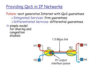
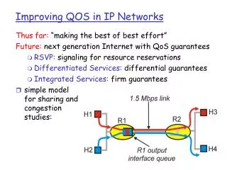
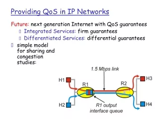
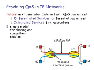
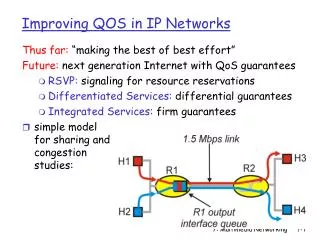
Improving QOS in IP Networks Thus far: “making the best of best effort” Future: next generation Internet with QoS guarantees • RSVP: signaling for resource reservations • Differentiated Services: differential guarantees • Integrated Services: firm guarantees • simple model for sharing and congestion studies: 7: Multimedia Networking
Principles for QOS Guarantees • Example: 1Mbps, I P phone, FTP share 1.5 Mbps link. • bursts of FTP can congest router, cause audio loss • want to give priority to audio over FTP Principle 1 packet marking needed for router to distinguish between different classes; and new router policy to treat packets accordingly 7: Multimedia Networking
Principles for QOS Guarantees (more) • what if applications misbehave (audio sends higher than declared rate) • policing: force source adherence to bandwidth allocations • marking and policing at network edge: • similar to ATM UNI (User Network Interface) Principle 2 provide protection (isolation) for one class from others 7: Multimedia Networking
Principles for QOS Guarantees (more) • Allocating fixed (non-sharable) bandwidth to flow: inefficient use of bandwidth if flows doesn’t use its allocation Principle 3 While providing isolation, it is desirable to use resources as efficiently as possible 7: Multimedia Networking
Principles for QOS Guarantees (more) • Basic fact of life: can not support traffic demands beyond link capacity Principle 4 Call Admission: flow declares its needs, network may block call (e.g., busy signal) if it cannot meet needs 7: Multimedia Networking
Summary of QoS Principles Let’s next look at mechanisms for achieving this …. 7: Multimedia Networking
What Can a Basic Router do to Packets? • Send it… • Delay it… • Drop it… • How they are done impacts Quality of Service • Best effort? Guaranteed delay? Guaranteed throughput? • Many variations in policies with different behavior • Rich body of research work to understand them • Limited Internet deployment • Many practical deployment barriers since Internet was best-effort to begin with, adding new stuff is hard • Some people just don’t believe in the need for QoS! Not enough universal support 7: Multimedia Networking
Router Architecture Assumptions • Assumes inputs just forward packets to outputs • Switch core is N times faster than links in a NxN switch • Resource contention occurs only at the output interfaces • Output interface has classifier, buffer/queue, scheduler components Buffer/ Queue Classifier Scheduler 1 2 7: Multimedia Networking
Internet Classifier • A “flow” is a sequence of packets that are related (e.g. from the same application) • Flow in Internet can be identified by a subset of following fields in the packet header • source/destination IP address (32 bits) • source/destination port number (16 bits) • protocol type (8 bits) • type of service (4 bits) • Examples: • All packets from OSU • All packets between OSU and Berkeley • All UDP packets from OSU ECE department • Classifier takes a packet and decides which flow it belongs to 7: Multimedia Networking
Buffer/Queue • Buffer: memory where packets can be stored temporarily • Queue: using buffers to store packets in an ordered sequence • E.g. First-in-First-Out (FIFO) queue Buffer Buffer Packet Packet Head Of Queue Packet Packet Packet Packet Packet Packet 7: Multimedia Networking
Buffer/Queue • When packets arrive at an output port faster than the output link speed (perhaps only momentarily) • Can drop all excess packets • Resulting in low performance • Or can hold excess packets in buffer/queue • Resulting in some delay, but better performance • Still have to drop packets when buffer is full • For a FIFO queue, “drop tail” or “drop head” are common policies, i.e. drop last packet to arrive vs drop first packet in queue to make room • A chance to be smart: Transmission of packets held in buffer/queue can be *scheduled* • Which stored packet goes out next? Which is more “important”? • Impacts quality of service 7: Multimedia Networking
Fair Rate Computation • Denote • C – link capacity • N – number of flows • ri – arrival rate • Max-min fair rate computation: • compute C/N • if there are flows i such that ri <= C/N, update C and N • if no, f = C/N; terminate • go to 1 • A flow can receive at most the fair rate, i.e., min(f, ri) 7: Multimedia Networking
f = 4: min(8, 4) = 4 min(6, 4) = 4 min(2, 4) = 2 8 10 4 6 4 2 2 Example of Fair Rate Computation • C = 10; r1 = 8, r2 = 6, r3 = 2; N = 3 • C/3 = 3.33 C = C – r3 = 8; N = 2 • C/2 = 4; f = 4 7: Multimedia Networking
Max-Min Fairness • Associate a weight wi with each flow i • If link congested, compute f such that f = 2: min(8, 2*3) = 6 min(6, 2*1) = 2 min(2, 2*1) = 2 8 (w1 = 3) 10 6 6 (w2 = 1) 2 2 2 (w3 = 1) 7: Multimedia Networking
Scheduler • Decides how the output link capacity is shared by flows • Which packet from which flow gets to go out next? • E.g. FIFO schedule • Simple schedule: whichever packet arrives first leaves first • Agnostic of concept of flows, no need for classifier, no need for a real “scheduler”, a FIFO queue is all you need • E.g. TDMA schedule • Queue packets according to flows • Need classifier and multiple FIFO queues • Divide transmission times into slots, one slot per flow • Transmit a packet from a flow during its time slot 7: Multimedia Networking
TDMA Scheduling flow 1 TDMA Scheduler Classifier flow 2 1 2 flow n Buffer management 7: Multimedia Networking
Priority Scheduling Priority scheduling: transmit highest priority queued packet • multiple classes, with different priorities • class may depend on marking or other header info, e.g. IP source/dest, port numbers, etc.. 7: Multimedia Networking
Round Robin Scheduling round robin scheduling: • multiple classes • cyclically scan class queues, serving one from each class (if available) 7: Multimedia Networking
Internet Today • FIFO queues are used at most routers • No classifier, no scheduler, best-effort • Sophisticated mechanisms tend to be more common near the “edge” of the network • E.g. At campus routers • Use classifier to pick out BitTorrent packets • Use scheduler to limit bandwidth consumed by BitTorrent traffic 7: Multimedia Networking
Achieving QoS in Statistical Multiplexing Network • We want guaranteed QoS • But we don’t want the inefficiency of TDMA • Unused time slots are “wasted” • Want to statistically share un-reserved capacity or reserved but unused capacity • One solution: Weighted Fair Queuing (WFQ) • Guarantees a flow receives at least its allocated bit rate 7: Multimedia Networking
WFQ Architecture flow 1 WFQ Scheduler Classifier flow 2 1 2 flow n Buffer management 7: Multimedia Networking
What is Weighted Fair Queueing? • Each flow i given a weight (importance) wi • WFQ guarantees a minimum service rate to flow i • ri = R * wi / (w1 + w2 + ... + wn) • Implies isolation among flows (one cannot mess up another) Packet queues w1 w2 R wn
water buckets t2 t1 w2 w3 w1 Intuition: Fluid Flow w1 water pipes w2 w3
Fluid Flow System • If flows can be served one bit at a time • WFQ can be implemented using bit-by-bit weighted round robin • During each round from each flow that has data to send, send a number of bits equal to the flow’s weight 7: Multimedia Networking
Flow 1 (w1 = 1) 100 Kbps Flow 2 (w2 = 1) Flow 1 (arrival traffic) 1 2 4 5 3 time Flow 2 (arrival traffic) 1 2 3 4 5 6 time Service in fluid flow system 3 4 5 1 2 1 2 3 4 5 6 time (ms) 0 10 20 30 40 50 60 70 80 Fluid Flow System: Example 1 7: Multimedia Networking
Fluid Flow System: Example 2 • Red flow has packets backlogged between time 0 and 10 • Backlogged flow flow’s queue not empty • Other flows have packets continuously backlogged • All packets have the same size link flows weights 5 1 1 1 1 1 0 2 4 6 8 10 15 7: Multimedia Networking
Fluid Flow System 60 50 30 Packets of size 10, 20 & 30 arrive at time 0 7: Multimedia Networking
Fluid Flow System 40 45 15 5 30 Packets: time 0 size 15 time 5 size 20 time 15 size 10 7: Multimedia Networking
Fluid Flow System 15 5 30 60 45 Packets: time 0 size 15 time 5 size 20 time 15 size 10 time 18 size 15 7: Multimedia Networking
Implementation in Packet System • Packet (Real) system: packet transmission cannot be preempted. Why? • Solution: serve packets in the order in which they would have finished being transmitted in the fluid flow system 7: Multimedia Networking
Select the first packet that finishes in the fluid flow system Packet System: Example 1 Service in fluid flow system 0 2 4 6 8 10 Packet system 0 2 4 6 8 10 7: Multimedia Networking
Select the first packet that finishes in the fluid flow system 1 2 1 3 2 3 4 4 5 5 6 Packet System: Example 2 Service in fluid flow system 3 4 5 1 2 1 2 3 4 5 6 time (ms) Packet system time 7: Multimedia Networking
Implementation Challenge • Need to compute the finish time of a packet in the fluid flow system… • … but the finish time may change as new packets arrive! • Need to update the finish times of all packets that are in service in the fluid flow system when a new packet arrives • But this is very expensive; a high speed router may need to handle hundred of thousands of flows! 7: Multimedia Networking
Finish times computed at time 0 time 0 1 2 3 Finish times re-computed at time ε time 0 1 2 3 4 Example • Four flows, each with weight 1 Flow 1 time Flow 2 time Flow 3 time Flow 4 time ε 7: Multimedia Networking
Solution: Virtual Time • Key Observation: while the finish times of packets may change when a new packet arrives, the order in which packets finish doesn’t! • Only the order is important for scheduling • Solution: instead of the packet finish time maintain the round # when a packet finishes (virtual finishing time) • Virtual finishing time doesn’t change when a packet arrives • System virtual time V(t) – index of the round in the bit-by-bit round robin scheme 7: Multimedia Networking
Example Flow 1 • Suppose each packet is 1000 bits, so takes 1000 rounds to finish • So, packets of F1, F2, F3 finishes at virtual time 1000 • When packet F4 arrives at virtual time 1 (after one round), the virtual finish time of packet F4 is 1001 • But the virtual finish time of packet F1,2,3 remains 1000 • Finishing order is preserved time Flow 2 time Flow 3 time Flow 4 time ε 7: Multimedia Networking
System Virtual Time (Round #): V(t) • V(t) increases inversely proportionally to the sum of the weights of the backlogged flows • Since round # increases slower when there are more flows to visit each round. Flow 1 (w1 = 1) time Flow 2 (w2 = 1) time 3 4 5 1 2 1 2 3 4 5 6 V(t) C/2 C 7: Multimedia Networking
Virtual Time Implementation of Weighted Fair Queueing • ajk – arrival time of packet k of flow j • Sjk– virtual starting time of packet k of flow j • Fjk– virtual finishing time of packet k of flow j • Ljk– length of packet k of flow j • BJ - backlog flow (flow with packets in queue) • Packets are sent in the increasing order of Fjk 7: Multimedia Networking
Properties of WFQ • Guarantee that any packet is transmitted within packet_length/link_capacity of its transmission time in the fluid flow system • Can be used to provide guaranteed services • Achieve fair allocation • Can be used to protect well-behaved flows against malicious flows
Policing Mechanisms 7: Multimedia Networking
Policing Mechanisms Goal: limit traffic to not exceed declared parameters Three common-used criteria: • (Long term) Average Rate:how many pkts can be sent per unit time (in the long run) • crucial question: what is the interval length: 100 packets per sec or 6000 packets per min have same average! • Peak Rate: e.g., 6000 pkts per min. (ppm) avg.; 1500 ppm peak rate • (Max.) Burst Size: max. number of pkts sent consecutively (with no intervening idle) 7: Multimedia Networking
Policing Mechanisms • Leaky Bucket Algorithm • Token Bucket Algorithm 7: Multimedia Networking
The Leaky Bucket Algorithm • The Leaky Bucket Algorithm used to control rate in a network. • Implemented as a single-server queue with constant service time. • If the bucket (buffer) overflows then packets are discarded. 7: Multimedia Networking
The Leaky Bucket Algorithm (a) A leaky bucket with water. (b) a leaky bucket with packets. 7: Multimedia Networking
The Leaky Bucket Algorithm • The leaky bucket enforces a constant output rate regardless of the burstiness of the input. Does nothing when input is idle. • The host injects one packet per clock tick onto the network. This results in a uniform flow of packets, smoothing out bursts and reducing congestion. • When packets are the same size (as in ATM cells), the one packet per tick is okay. For variable length packets though, it is better to allow a fixed number of bytes per tick. 7: Multimedia Networking
Token Bucket Token Bucket: limit input to specified Burst Size and Average Rate. • bucket can hold b tokens • tokens generated at rate r token/sec unless bucket full • over interval of length t: number of packets admitted less than or equal to (r t + b). 7: Multimedia Networking
Token Bucket • Characterized by three parameters (b, r, R) • b – token depth • r – average arrival rate • R – maximum arrival rate (e.g., R link capacity) • A bit is transmitted only when there is an available token • When a bit is transmitted exactly one token is consumed r tokens per second bits slope r b*R/(R-r) b tokens slope R <= R bps time regulator 7: Multimedia Networking
Characterizing a Source by Token Bucket • Arrival curve – maximum amount of bits transmitted by time t • Use token bucket to bound the arrival curve bps bits Arrival curve time time 7: Multimedia Networking
(b=1,r=1,R=2) Example • Arrival curve – maximum amount of bits transmitted by time t • Use token bucket to bound the arrival curve Arrival curve bits 4 bps 3 2 2 1 1 0 1 2 3 4 5 1 2 3 4 5 time size of time interval 7: Multimedia Networking
token rate, r arriving traffic bucket size, b per-flow rate, R WFQ D = b/R max Policing Mechanisms • token bucket, WFQ combine to provide guaranteed upper bound on delay, i.e., QoS guarantee! 7: Multimedia Networking