Download
1 / 27
290 likes | 522 Vues
Airborne Observation of the Hayabusa Sample Return Capsule Re-entry. Jay Grinstead NASA Ames Research Center Moffett Field, CA Peter Jenniskens and Jim Albers The SETI Institute Mountain View, CA Alan Cassell ERC Incorporated Moffett Field, CA Michael Winter

E N D
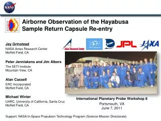
Airborne Observation of the Hayabusa Sample Return Capsule Re-entry Jay Grinstead NASA Ames Research Center Moffett Field, CA Peter Jenniskens and Jim Albers The SETI Institute Mountain View, CA Alan Cassell ERC Incorporated Moffett Field, CA Michael Winter UARC, University of California, Santa Cruz Moffett Field, CA International Planetary Probe Workshop 8 Portsmouth, VA June 7, 2011 Support: NASA In-Space Propulsion Technology Program (Science Mission Directorate)
Hayabusa re-entry video • q http://airborne.seti.org/hayabusa/images/CCO-postflight.mp4
Hayabusa sample return capsule (SRC) re-entry observation • Flight experiment of an atmospheric entry vehicle • Significant interest to NASA: EDL technology development • Rare opportunity to observe performance of integrated entry system under known conditions conditions • Trajectory, Shape, TPS material • Airborne observation of re-entry event • Proven way to obtain quantitative radiance data, spectrally and temporally resolved, from a flight experiment (e.g. Stardust) • NASA’s DC-8 airborne laboratory • Flight data are critical for validation of simulation tools used for entry systems design and development • High-fidelity CFD and engineering aerothermal simulations • TPS material response • Radiation transport • Contributes to ground and flight database of atmospheric entry phenomenology
Hayabusa mission • JAXA mission launched May 9, 2003 to explore and return sample from near-earth asteroid Itokawa (1998 SF36) • Rendezvous and sample collection Sept–Nov 2005 • Sample return capsule (SRC) re-entered on June 13, 2010 at Woomera Test Range, South Australia
Hayabusa sample return capsule • 45˚ sphere-cone • 0.40 m (15.8”) dia. • 16.3 kg (36 lbs) • Carbon phenolic TPS (forebody and backshell) JAXA
Hayabusa return trajectory Entry at 13:51 UTC (11:21 pm local) June 13, 2010 Woomera Prohibited Area
EDL and recovery JAXA
Re-entry trajectory and heat pulse • Entry velocity 12.2 km/s (second fastest Earth re-entry) • Aeroheating environment similar to Stardust • Results were used for observation planning • Brightness estimation • Flight path optimization • Target acquisition cueing
Previous airborne observations Stardust – 2006 • Leveraged experience from previous airborne observation campaigns • Spacecraft re-entry • Meteor showers • NASA Ames, SETI Institute and collaborators • Mature instrument suite • Seasoned researchers • Successful flight path planning Leonids – 2002 ATV – 2008
Optical instrumentation • Imaging instruments • HDTV • Intensified CCDs • Digital cinematography cameras • Spectral instruments • Slitless spectrographs • High resolution slit spectrographs • Time resolved • 1 to 1000 Hz framing rates • Synchronized to GPS universal time reference • 25 instrument platforms • 51 cameras total
Spectral instruments: wavelength span and resolution N2, N2+, CN, Ca+ N, O, H, C, Na • Low resolution • Surface thermal radiation • High resolution • Line and band shape analysis, shock radiation Xybion DIM SPOSH WISP FIPS SLIT NIRSPEC ASTRO IRIS2 IUV LDVS HDVS HFRS (high frame rate) TERAS (high frame rate) IRIS1 AUS ECHELLE Slitless Slit Echelle Slitless, color CCD
Re-entry trajectory and DC-8 flight path Hayabusa trajectory Peak heating ~57 km Woomera Prohibited Area DC-8 Observation Leg Fight path planning: A. Cassell – Session 6B, 10:30 am Thursday 13
Capsule – bus separation • Estimated at approx. 5 km • Significant lateral displacement was not expected • Enabled discrimination of capsule spectra from bus fragments 13:52:20 UT (THDTV) J. Carpenter (Ames/Planners)
Spectral movie: temporal evolution from three instruments • a
Spectral movie: temporal evolution from three instruments • x R. Dantowitz et al., CCO
Example composite capsule spectrum • Four instruments • Preliminary calibration – no atmospheric absorption correction • Altitude: 64 km, speed: 11.3 km/s • Prior to peak heating • Species identification • Shock radiation • Ablation products PRELIMINARY
Summary and forward plan • Successful airborne observation • Data will be compared with high fidelity simulation tools for entry aerothermodynamics • Near perfect performance of airborne instrumentation • Confirms mission planning methodologies • Project was an international effort • NASA (Ames, JPL, JSC, LaRC, and Headquarters) • SETI Institute • JAXA • Australian civil and defense authorities • Science team members from US, Europe, Japan, and Australia • Future activities • Complete data analysis and comparison with simulations • Special Hayabusa session at 2012 AIAA ASM in Nashville
On the way home • h
Hayabusa sample return capsule re-entry observationMotivation • Flight experiment of an atmospheric entry vehicle • Significant interest to NASA: EDL technology development • Rare opportunity to observe performance of integrated entry system under known conditions conditions • Trajectory, Shape, TPS material • Airborne observation of re-entry event • Proven way to obtain quantitative radiance data, spectrally and temporally resolved, from a flight experiment • Flight data are critical for validation of simulation tools used for entry systems design and development • High-fidelity CFD and engineering aerothermal simulations • TPS material response • Radiation transport
Hayabusa sample return capsule re-entry observationObjectives and methods • Obtain total and spectrally resolved emission during luminous period of re-entry • Calibrated instruments for measurements of absolute spectral irradiance • Time-resolved: synchronized to common time reference (UTC) • Obtain as-flown trajectory • Latitude, longitude, altitude, time: critical for correlation with optical data • Multi-instrument Aircraft Campaign (MAC) • Instrumentation aboard NASA’s DC-8 airborne laboratory to observe SRC entry radiation • Instruments acquire total and spectrally radiated power from SRC shock layer and heat shield surface during re-entry • Multiple ground observations • Trajectory reconstruction by triangulation • Similar to Stardust sample return observation (2006)
Project organization In-Space Propulsion Technology Program David Anderson, PM (GRC) David Hahne, Aerocapture PM (LaRC) NASA Ames Research Center Jay Grinstead, Project Manager Alan Cassell, Systems Engineer Dean Kontinos, Consulting Engineer Instruments SETI Institute Peter Jenniskens, Principal Investigator | Sub-contract to various instrument PIs DC-8 NASA Dryden Aircraft Operations Facility Frank Cutler, Mission Manager Pre- and Post-Flight Analysis NASA Ames Research Center Michael Winter Gary Allen Ryan McDaniel Y.K. Chen NASA Johnson Space Center Space Meteorology Group NASA Jet Propulsion Laboratory Tommy Thompson, PM Rob Haw (trajectory) Shyam Bhaskaram (trajectory) JAXA ISAS Tetsuya Yamada (mission support) Woomera Test Range John McKevett Ian Tuohy NASA Headquarters Office of External Relations
DC-8 Airborne Laboratory • Operated by NASA Dryden Aircraft Operations Facility (Palmdale, CA) • Accommodates a variety of optical instrumentation • Large frame windows with optical-grade materials • Power, data, timing infrastructure for instrument platform integration • Flies up to 12 km (41,000 ft) altitude • Above most clouds and weather; reduces atmospheric absorption • 12 hour endurance
Instrument platform layout • Most windows had optical quality materials • Instruments on port side of aircraft • Universal Time (UTC) provided to instruments via aircraft GPS receiver
Mission deployment schedule • June 1-7: NASA Dryden Aircraft Operations Facility (Palmdale, CA) • Instrument upload, integration, and calibration • June 8: Depart for Melbourne via Hickam AFB (Honolulu, HI) • June 11: Arrive Melbourne • June 13: Re-entry observation • June 15: Return to Palmdale via Hickam AFB • June 16: Arrive Palmdale • Second instrument calibration, instrument download
Ground and flight operations schedule • 1-4 June: Instrument upload and ground checks • 4 June: Instrument check flight • 11 June: Equipment tests • 12 June: Test flight • 13 June: Science flight • 14 June: Post-flight tarmac tests
Flight path planning • Objective: capture SRC emission from first detection through peak heating (preferably beyond) • Three primary variables to optimize • Slant range distance (aircraft to SRC) • Duration of track within aircraft window field of view • Time-on-target to initial way point of observation leg • Constraints guiding optimization • Expected small bus-SRC separation distance (favors wide angle from trajectory) • Near-frontal view through peak heating (favors narrow angle from trajectory) • 60 km exclusion zone either side of ground track • Brightness vs. transit time in field of view (i.e. distance to target) • Winds aloft