Download
1 / 16
190 likes | 571 Vues
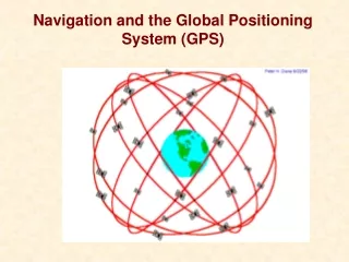
Global Positioning System Integrated with an Inertial Navigation System. Michael Bekkala Michael Blair Michael Carpenter Matthew Guibord Abhinav Parvataneni Dr. Shanker Balasubramaniam. Inertial Navigation System. The use of inertial measurements in navigation

E N D
Global Positioning System Integrated with an Inertial Navigation System Michael Bekkala Michael Blair Michael Carpenter Matthew Guibord Abhinav Parvataneni Dr. Shanker Balasubramaniam
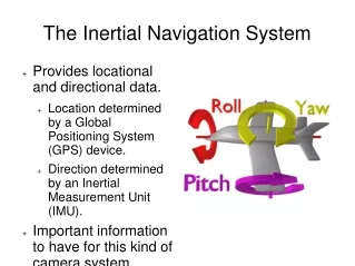
Inertial Navigation System • The use of inertial measurements in navigation • Measurements come from inertial sensors such as: • Accelerometers • Gyroscopes • Very accurate over short term • Errors integrate with time
Physics of Accelerometers/Gyroscopes • Accelerometers • Measure acceleration in x, y, z directions • Types: • Mechanical • Micro Electromechanical (MEMS) • Capacitive • Piezoelectric
Mechanical Accelerometers Picture from “Basic Inertial Navigation” by Sherryl Stoval Mass suspended in a case by a pair of springs Acceleration along the axis of the springs displaces the mass. This displacement is proportional to the applied acceleration
Capacitive Accelerometers http://www.sensorland.com/HowPage011.html Sense a change in capacitance with respect to acceleration Diaphragm acts as a mass that undergoes flexure Two fixed plates sandwich diaphragm, creating two capacitors Change in capacitance by altering distance between two plates
Piezoelectric Accelerometers Commonly uses 1 crystal made of quartz Force exerted by acceleration changes electrostatic force Low output signal and high output impedance requires the use of amplifiers Picture from Wikipedia.org
Physics of Accelerometers/Gyroscopes • Gyroscopes • Measure Angular velocity in yaw, pitch, and roll directions • Micro Electromechanical (MEMS) • Optical
Micro Electromechanical Gyroscopes • Coriolis effect • Vibrating elements measure • Coriolis effect (vibrations on • sense axis) • When rotated, 2nd vibration on the drive axis • Angular Velocity Picture from http://www.howyourelectronicswork.com/2008/09/fiber-optic-gyroscopes.html
Optical Gyroscopes • Sends out two beams of light • Sensor can detect interference in the light beam • Very accurate • No inherent drift • Expensive
Navigation Equations • Accelerations and angular velocities are measured in the body coordinate frame • Need a constant reference for navigation • Rotation from bodyframe to North, East,Down frame gives areference. Picture from “Accuracy and Improvement of Low Cost INS/GPS for Land Applications” by Shin
Inertial Navigation System System View of INS Equations Diagram from Basic Inertial Navigation by Sherryl Stovall
Navigation Equations • The navigation equations can be represented as (Shin, 2001):
Navigation Equations • BodyNED
Navigation Equations • GPS and INS need to be in the same reference frame for proper measurements. • GPS data is in Earth Centered Earth Fixed (ECEF) • INS data is in Body frame and has to be translated to the North-East-Down frame • BodyNED, ECEFNED Picture from “Accuracy and Improvement of Low Cost INS/GPS for Land Applications” by Shin
Integration of GPS and INS • Different integration levels: • Loosely Coupled • Corrects errors in the IMU and INS • Does not correct GPS • Tightly Coupled • Corrects both INS and GPS errors • Kalman filtering integrates both systems to achieve a more accurate overall system
GPS/INS Integration System View of Integration Diagram from http://inderscience.metapress.com/media/59dam5dyxldjpg54uc5v/contributions/8/3/w/2/83w217t06m878447.pdf