Download
1 / 25
250 likes | 354 Vues
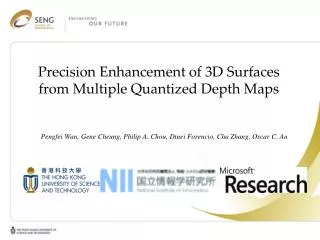
This paper presents a novel approach to improving the precision of 3D surfaces derived from quantized depth maps. By leveraging novel machine learning techniques, we propose a decoding scheme that enhances depth map resolution while accommodating various compression methods. Our method works with pairs of color and depth maps captured from two viewpoints. Through experiments, we demonstrate significant improvements in depth representation and quality, contributing to more accurate dynamic 3D scene representations. The approach emphasizes identifying true intersection cells to reduce uncertainty and enhance overall detail.

E N D
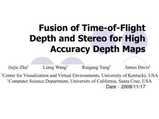
Precision Enhancement of 3D Surfacesfrom Multiple Quantized Depth Maps Pengfei Wan, Gene Cheung, Philip A. Chou, DineiForencio, Cha Zhang, Oscar C. Au
OUTLINE • Motivation • Assumptions & Definitions • Problem Formulation • Proposed ML Solution • Experiments • Conclusions
Motivation • texture-plus-depth: dynamic 3D scene representation • high (bit-)precision depth map better DIBR quality
Motivation • Scene depth d is quantized during acquisition & compression. • acquisition: true d istypically represented as integer pixel valueby depth-sensor. • compression: depth maps may be lossy-compressed (e.g. block-based DCT). • In this paper • we design a decoding scheme such that <! • it works for any depth map compression scheme. (w/ assumption that • quantization bin per-pixel can be inferred) • d
Motivation • We consider a scenario where • input: • -bit quantized color + depth maps (2 views) • output: • depth maps with enhanced precision> + L view + R view
Motivation Key fact: texture-plus-depth maps of two views are redundant representation describing the same 3D scene, or they constitute multiple descriptions (MD) of the same signal. Scalar Quantizers MD for a 3D scene enhanced precision = reduced uncertainty intersection of quantization bins from MD
OUTLINE • Motivation • Assumptions & Definitions • Problem Formulation • Proposed ML Solution • Experiments • Conclusions
Definitions • (Intersection ) Cell: intersection of two (active) QBs. • an active QB may have multiple ICs. voxel : point in the 3D scene that is captured everydepth pixel corresponds to a QB in 3D space
Assumptions • asp#1: the color + depth map pairs are rectified. • *so that each pixel row corresponds to a 2D epipolar plane. • asp#2:the spatial resolution is sufficiently high. • *same voxel in 3D scene (if visible) is sampled by both views. • asp#3:near Lambertian surface for the 3D scene. • *color of same voxel in 3D scene in two views should be close.
OUTLINE • Motivation • Assumptions & Definitions • Problem Formulation • Proposed ML Solution • Experiments • Conclusions
Problem Formulation ++> • IC is called true if it contains a voxel of the actual 3D surface. • IC is by definition smaller than QBin size (smaller uncertainty). depth map precision enhancement identifying true ICs in QBs
Deterministic & Probabilistic ICs • Special case: • ICs satisfying Lemma1 can be certified as true (called deterministic ICs) using geometric information only. • General case: • The rest ICs are probabilistic ICs. We will use color information to select true ICs within probabilistic ICs. • *Lemma 1. is true if it is the only IC of QB and other cells of are not occluded by active QBs in right view (and vice versa).
OUTLINE • Motivation • Assumptions & Definitions • Problem Formulation • Proposed ML Solution • Experiments • Conclusions
Proposed ML Solution To identify true probabilistic ICs: Step#1. divide QBs on an epipolar plane into segments (different objects). *contiguity of quantized curve can be enforced within a segment. Step#2. each segment is further divided into several process units (PU). *each PU has a start cell and an end cell. Step#3. for each PU, estimate a contiguous ML quantized curve. *a quantized curve is a spatially contiguous series of QBs (at low precision) or ICs (at high precision).
Proposed ML Solution • After Step#1 & Step#2 • each PU has a start cell and an end cell. • a quantized curve is estimated for each PU. • start/end cell is marked in yellow. • black lines connect the ICs and QBs in estimated quantized curve.
Proposed ML Solution Step#3. estimate a ML quantized curve for each PU. For a given PU construct a graph where each IC is a node connected to its neighbors. for a specific IC (with associated color in left and right views), we define: 3. given color info, our goal is to find the ML quantized curve —a most likely ordered set of nodes C = {, . . . ,} that maximizes the color matching where is the feasible set of quantized curves. ML quantized curve estimation Solving (1)
Proposed ML Solution • How to solve (1)? • Assume that probabilities of nodes in C are independent, (1) becomes: Solving (1) Solving (2)
Proposed ML Solution • How to solve (2)? • (2) is essentially a sum of edge-weights along a contiguous path • In particular, if we set the weight of an edge arriving at as • (e.g. ) (2) can be easily solved using shortest path algorithm (e.g. Dijkstra) !!
Proposed ML Solution • Brief summary: • for a PU with start/end cells, we make use of the available color info to select • a most likely connected path of ICs using a shortest path algorithm. • combining ML quantized curves for all PUs in all segments on all epipolar planes, • we arrive at a quantized 3D surface with enhanced precision.
OUTLINE • Motivation • Assumptions & Definitions • Problem Formulation • Proposed ML Solution • Experiments • Conclusions
Experiments • Test sequences: sphere (400 × 400) and dude (480 × 800) • Experiment setup: • depth maps with 3-bit∼6-bit precision (d3∼d6) • color maps with 6-bit or 8-bit precision (c6 & c8). • Depth decoding • standard method: center depth values of QBs. • proposed method: center values of ICs (or QBs). • Metric:mean square error (MSE)
Experiments MSE of proposed method is smaller than that of standard method.
Experiments Example of decoded surface of proposed method (green spots) and ground-truth (black crosses) for dude with 6-bit depth and 6-bit color
Conclusions • Enhance the bit-precision of decoded depth maps. • *ML-optimal solution use geometric and color info • Our method is computation-efficient. • *involving only shortest path algorithms • 3. It can be extended to more than 2 views. • Knowledge can be leveraged at the encoder.
Thank you ! Q&A Contact Information: leoman@ust.hk, cheung@nii.ac.ni.jp, pachou@microsoft.com, dinei@microsoft.com, chazhang@microsoft.com, eeau@ust.hk