Two Wheels Self Balancing Robot
Southern Taiwan University Department of Electrical Engineering. Two Wheels Self Balancing Robot. Professor : Chi-Jo Wang Student’s name : Nguyen Van Binh Student ID : MA02B203. CONTENT . Overview of two wheel balancing robot Dynamic model PID controller Implement

Two Wheels Self Balancing Robot
E N D
Presentation Transcript
Southern Taiwan University Department of Electrical Engineering Two Wheels Self Balancing Robot Professor : Chi-Jo Wang Student’s name : Nguyen Van Binh Student ID : MA02B203
CONTENT • Overview of two wheel balancing robot • Dynamic model • PID controller • Implement • Conclusion
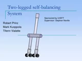
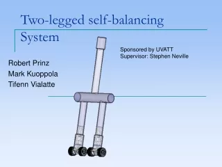
Overview of two wheel balancing robot Two wheel balancing robot based on inverted pendulum model. Inverted pendulum model is a complex nonlinear object. In recent years there have been many projects about the application of inverted pendulum principle to make two wheel self balancing robot.
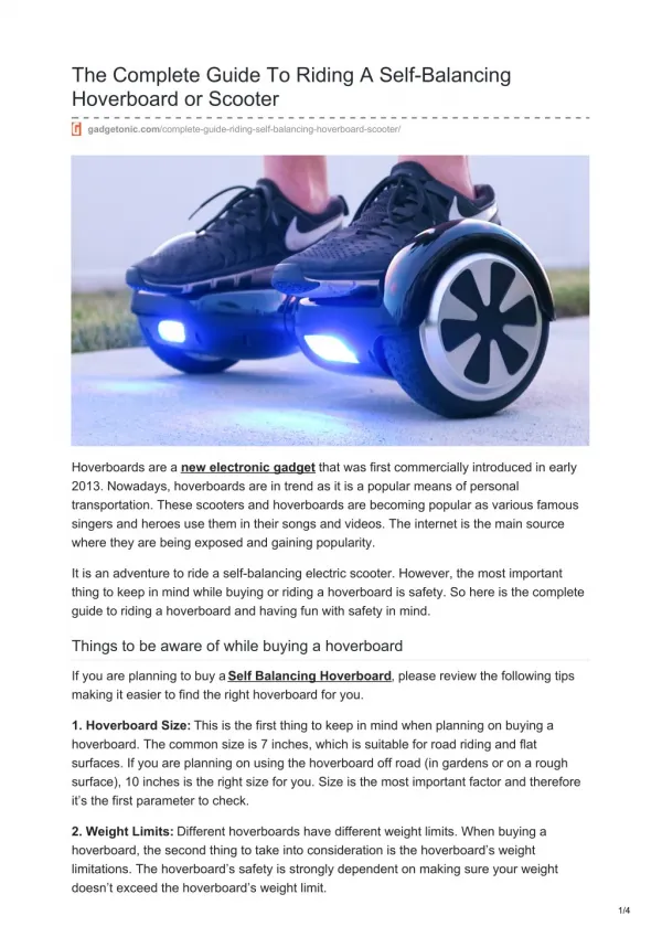
Overview of two wheel balancing robot A robot that is capable of balancing upright on its two wheels is known as a two wheeled balancing robot. The process of balancing is typically referred to as stability control. The two wheels are situated below the base and allow the robot chassis to maintain an upright position by moving in the direction of tilt, either forward or backward, in an attempt to keep the centre of the mass above the wheel axles. The wheels also provide the locomotion thus allowing the robot to transverse across various terrains and environments.
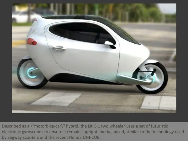
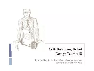
Overview of two wheel balancing robot Some applications of two wheels balancing robot
Dynamic model Two wheels balancing robot based on inverted pendulum dynamic model. So, research about inverted pendulum dynamic model is necessary in modeling robot . Consider inverted pendulum dynamic model as following:
Dynamic model With O-I signals block diagram of model Inverted pendulum system
Dynamic model Suppose (xp; yp) is coordinate of m heavy at the top of the pendulum, we have: Applying Newton's II law of motion in the x, we have:
Dynamic model Change xp in [2-1] into [2-3], we have: Implement calculating from [2-4] Applying Newton's II Law for rotation of the pendulum around axis
Dynamic model From [2-1], [2-2], [2-6] we have: Implement calculating from [2-7] From [2-5] and [2-8] easy to have:
Dynamic model Suppose F = u Set state-space, we have:
Dynamic model Balance point at the vertical position: Linear around at the balance point: With:
PID Controller PID is “Proportional, Integral, and derivative”. PID is the three- term controller. PID controller based on a feedback control method.
PID Controller Process is a controlled object. The purpose of control is to make the output y (PV) followed r set point (set point-SP). To do this, the controller will get the error between output signal and input signal and then through the stages of control to make control signals accordingly, to minimize this error. A proportional controller (Kp) will have the effect of reducing the rise time and will reduce ,but never eliminate, the steady-state error. An integral control (Ki) will have the effect of eliminating the steady-state error, but it may make the transient response worse. A derivative control (Kd) will have the effect of increasing the stability of the system, reducing the overshoot, and improving the transient response
PID Controller 1. Proportional control Proportional control generate the changes of output. This change is proportional to the bias current value. Response of Proportional control can be adjusted multiplying the difference signal with Kp. Pout = Kp.e(t) with Kp is Gain e is error = SP-PV t is current time
PID Controller With larger Kp value is easy to adjust error. However, the system lost stability. Kp is too small then the system will react very slowly with the input error
PID Controller 2. Integral control The value adjusted at Integral control is proportional with bias in a period of time. It is total of bias. This signal are then multiplied by the integral gain Ki and taken to adjust output With Ioutis the integral of output Ki is Gain of the integral e is error = SP-PV t is current time
PID Controller Integral control in PID controller increase process to output close SP value and eliminate setting error of proportional control. However, Integral control added up all bias in stages before, so It is cause of overshoot.
PID Controller 3. Derivative control Derivative control will determine the rate of change of error. With Doutis the derivative of output Kd is Gain of the derivative e is error = SP-PV t is current time
PID Controller Integral control in PID controller increase process to output close SP value and eliminate setting error of proportional control. However, Integral control added up all bias in stages before, so It is cause of overshoot.
Accelerometer PIN9V Gyro Source 5V Microcontroller ATMEGA32 IR Receiver L298 PIN 9Vx2 Left wheel motor Right wheel motor Implement Figure 4.1 Block Diagram two wheel balancing robot
Conclusions This project was successful in achieving its aims to balance a two-wheeled autonomous robot based on the inverted pendulum model. The Kalman filter has been successfully implemented. The gyroscope drift was effectively eliminated allowing for an accurate estimate of the tilt angle and its derivative for the robot. More research is needed to investigate the effects of linearising the dynamics of the system mode to improve the stability and robustness of the robot. An attempt to control the system using nonlinear methods is highly recommended for future research
References [1] Anderson, DP, 2007, nBot Balancing Robot, viewed 20 Th March 2008, <http://www.geology.smu.edu/~dpa www/robo/nbot/> [2] Andrade-Cetto, J & Sanfeliu, A 2006, Environment Learning for Indoor Mobile Robots, Springer, New York. [3] Angeles, J 2007, Fundamentals of Robotic Mechanical Systems, Springer, New York. [4] Banks, D 2006, Microengineering MEMs and Interfacing, Taylor & Francis, London. [5] Bates, Hellebuyck, Ibrahim, Jasio, D, Morton, Smith, D, Smith, J & Wilmshurst 2008, PIC Microcontroller, Elsevier Inc, New York. [6] Bergren, C 2003, Anatomy of a Robot, McGraw-Hill, Sydney. [7] Bishop, R 2002, The Mechatronics Handbook, CRC Press, London. [8] Bishop, R 2006, Mechatronics - An Introduction, Taylor & Francis, London. [9] Bokor, J, Hangos, K & Szederkenyi, G 2004, Analysis & Control of Nonlinear Process Systems, Springer, New York. [10] Braunl, T 2006, Embedded Robotics, Springer, Perth.